Nissan Titan A60. Manual - part 172
BRC-66
< DTC/CIRCUIT DIAGNOSIS >
[VDC/TCS/ABS]
C1160 DECEL G SEN SET
C1160 DECEL G SEN SET
Description
INFOID:0000000006165901
The yaw rate/side/decel G sensor detects the yaw rate/side/decel G affecting the vehicle, and transmits the
data to the ABS actuator and electric unit (control unit) as an analog voltage signal.
DTC Logic
INFOID:0000000006165902
DTC DETECTION LOGIC
DTC CONFIRMATION PROCEDURE
1.
CHECK SELF-DIAGNOSIS RESULTS
Check the self-diagnosis results.
Is above displayed on the self-diagnosis display?
YES
>> Proceed to diagnosis procedure. Refer to
.
NO
>> Inspection End
Diagnosis Procedure
INFOID:0000000006165903
1.
PERFORM SELF-DIAGNOSIS
Perform ABS actuator and electric unit (control unit) self-diagnosis. Refer to
Do self-diagnosis results indicate anything other than shown above?
YES
>> Perform repair or replacement for the item indicated.
NO
>> Perform calibration of decel G sensor. Refer to
BRC-9, "CALIBRATION OF DECEL G SENSOR :
. GO TO 2
2.
PERFORM SELF-DIAGNOSIS AGAIN
1. Turn the ignition switch to OFF and then to ON and erase self-diagnosis results. Refer to
2. Perform ABS actuator and electric unit (control unit) self-diagnosis again. Refer to
.
Are any self-diagnosis results displayed?
YES
>> Replace yaw rate/side/decel G sensor. Refer to
BRC-119, "Removal and Installation"
NO
>> Inspection End
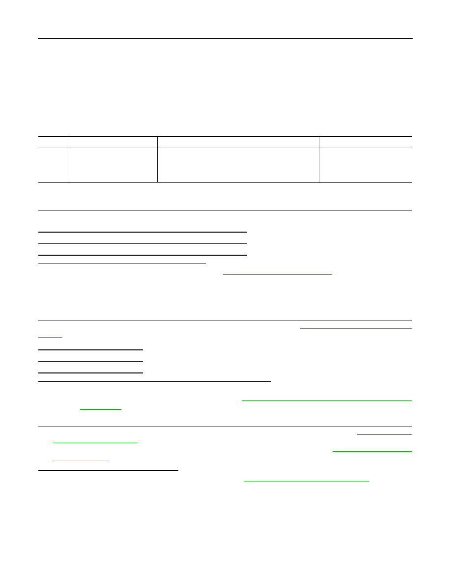
DTC
Display item
Malfunction detected condition
Possible cause
C1160
DECEL G SEN SET
ABS decel G sensor adjustment is incomplete.
• Decel G sensor calibration
• Yaw rate/side/decel G sensor
• ABS actuator and electric unit
(control unit)
Self-diagnosis results
DECEL G SEN SET
Self-diagnosis results
DECEL G SEN SET