Nissan Titan A60. Manual - part 132
BCS-8
< SYSTEM DESCRIPTION >
[BCM]
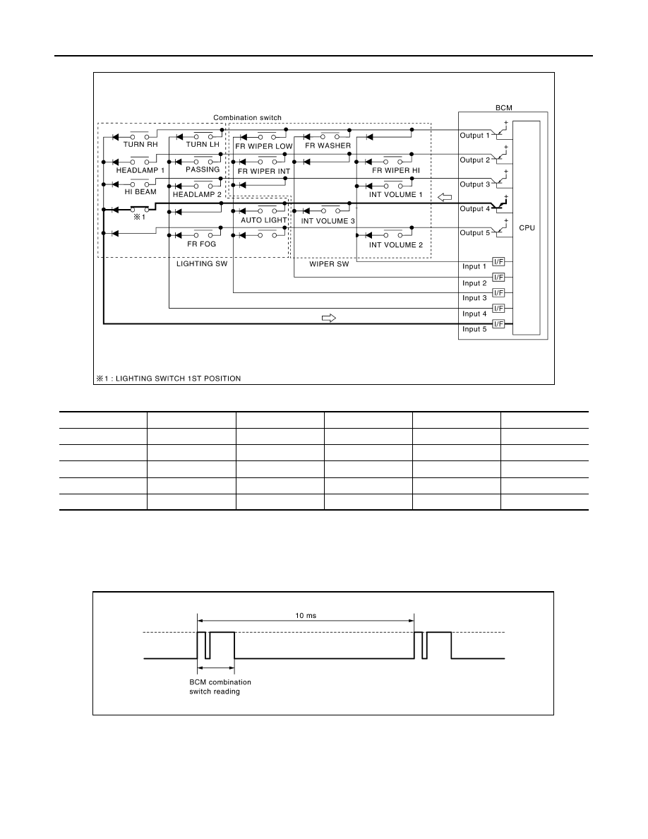
COMBINATION SWITCH READING SYSTEM
Combination switch circuit
Combination switch INPUT-OUTPUT system list
NOTE:
Headlamp has a dual system switch.
COMBINATION SWITCH READING FUNCTION
Description
• BCM reads the status of the combination switch at 10 ms interval normally.
NOTE:
BCM reads the status of the combination switch at 20 ms interval when BCM is controlled at low power con-
sumption control mode.
• BCM operates as follows and judges the status of the combination switch.
- INPUT 1 - 5 outputs the voltage waveforms of 5 systems simultaneously.
- It operates the transistor on OUTPUT side in the following order: OUTPUT 5
→ 4 → 3 → 2 → 1.
System
OUTPUT 1
OUTPUT 2
OUTPUT 3
OUTPUT 4
OUTPUT 5
INPUT 1
—
FR WASHER
FR WIPER LOW
TURN LH
TURN RH
INPUT 2
FR WIPER HI
—
FR WIPER INT
PASSING
HEADLAMP 1
INPUT 3
INT VOLUME 1
—
—
HEADLAMP 2
HI BEAM
INPUT 4
—
INT VOLUME 3
AUTO LIGHT
—
TAIL LAMP
INPUT 5
INT VOLUME 2
—
—
FR FOG
—
LIIA1325E
JPMIA0067GB