Nissan Titan A60. Manual - part 133
BCS-12
< SYSTEM DESCRIPTION >
[BCM]
SIGNAL BUFFER SYSTEM
SIGNAL BUFFER SYSTEM
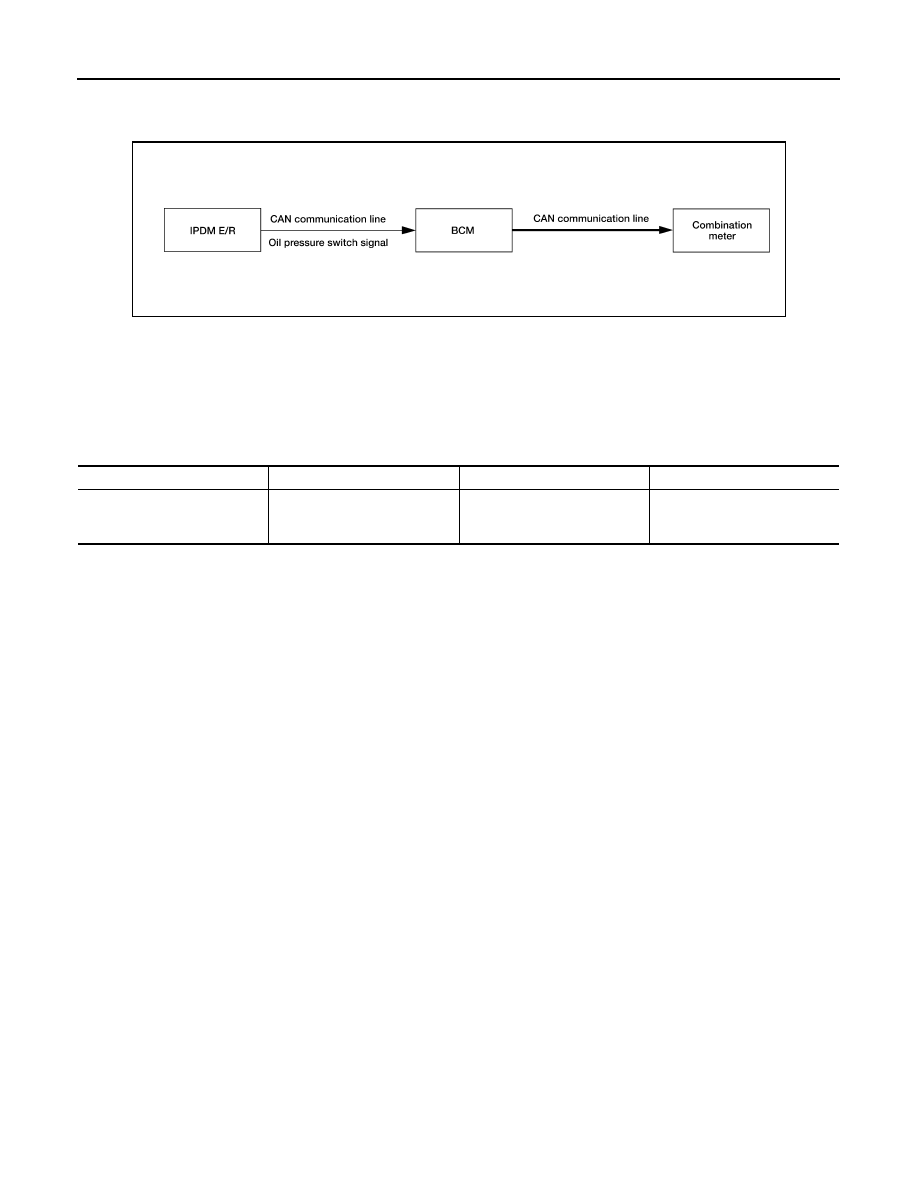
System Diagram
INFOID:0000000006161316
System Description
INFOID:0000000006161317
OUTLINE
BCM has the signal transmission function that outputs/transmits each input/received signal to each unit.
Signal transmission function list
ALMIA0263GB
Signal name
Input
Output
Description
Oil pressure switch signal
IPDM E/R (CAN)
Combination meter (CAN)
Transmits the received oil pres-
sure switch signal via CAN
communication.