Nissan Titan A60. Manual - part 101
AV
POWER SUPPLY AND GROUND CIRCUIT
AV-229
< DTC/CIRCUIT DIAGNOSIS >
[PREMIUM WITH NAVIGATION]
C
D
E
F
G
H
I
J
K
L
M
B
A
O
P
YES
>> Refer to
AV-227, "DVD PLAYER : Diagnosis Procedure"
NO
>> Repair harness or connector.
3.
CHECK GROUND CIRCUIT
1. Turn ignition switch OFF.
2. Disconnect video monitor connector.
3. Check continuity between video monitor harness connector
R202 and ground.
Does continuity exist?
YES
>> Inspection End.
NO
>> Repair harness or connector.
AUDIO AMP
AUDIO AMP : Diagnosis Procedure
INFOID:0000000006166583
Regarding Wiring Diagram information, refer to
AV-285, "Wiring Diagram - With Navigation System"
1.
CHECK FUSE
Check that the audio amp. fuses are not blown.
Are the fuses OK?
YES
>> GO TO 2.
NO
>> Be sure to eliminate cause of malfunction before installing new fuse.
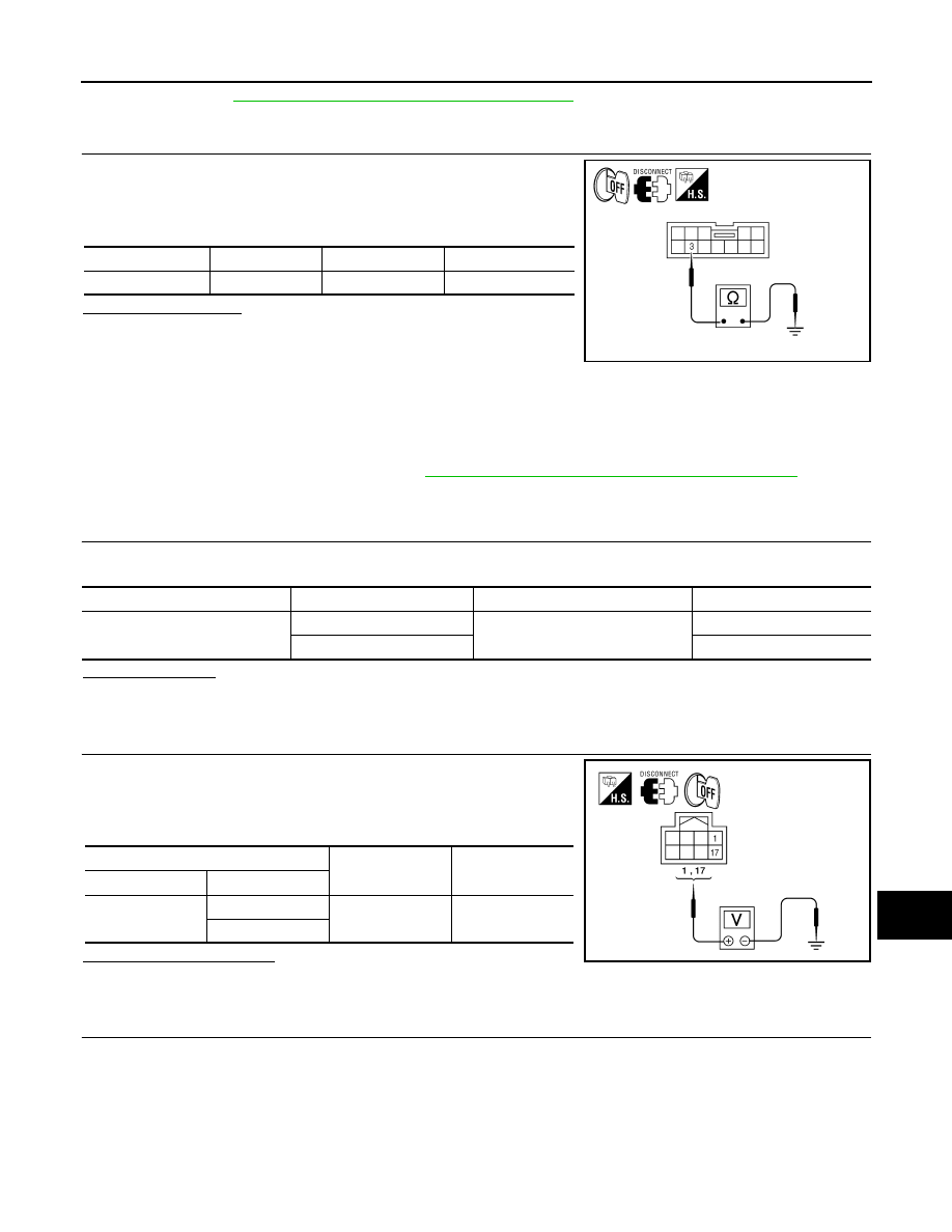
2.
CHECK POWER SUPPLY CIRCUIT
1. Turn ignition switch OFF.
2. Disconnect audio amp. connector.
3. Check voltage between audio amp. harness connector M112
and ground.
Is battery voltage present?
YES
>> GO TO 3.
NO
>> Check harness between audio amp. and fuse.
3.
CHECK GROUND CIRCUIT
Connector
Terminal
—
Continuity
R202
3
Ground
Yes
ALNIA0701GB
Unit
Terminal
Signal name
Fuse No.
Audio amp.
1
Battery power
31
17
17
(+)
(-)
Voltage (approx.)
Connector
Terminal
M112
1
Ground
Battery voltage
17
ALNIA0754GB