Nissan Titan A60. Manual - part 102


  Index      Nissan     Nissan Titan A60 (2011 year) - Service and Repair Manual


Search            


Content   ..  100  101  102  103   ..


Nissan Titan A60. Manual - part 102


AV

RGB (R: RED) SIGNAL CIRCUIT

AV-233

< DTC/CIRCUIT DIAGNOSIS >

[PREMIUM WITH NAVIGATION]

C

D

E

F

G

H

I

J

K

L

M

B

A

O

P

RGB (R: RED) SIGNAL CIRCUIT

Description

INFOID:0000000006166586

Transmit the image displayed with display control unit with RGB signal to the display unit.

Diagnosis Procedure

INFOID:0000000006166587

Regarding Wiring Diagram information, refer to 

AV-285, "Wiring Diagram - With Navigation System"

.

1.

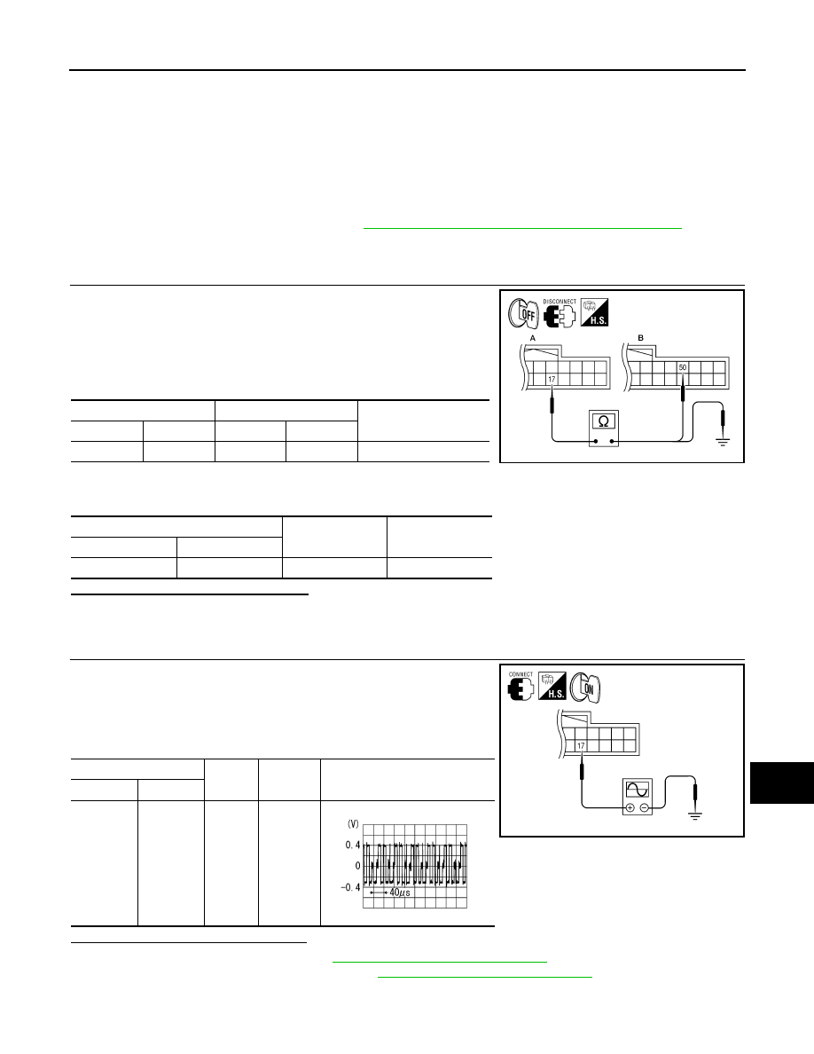
CHECK CONTINUITY RGB (R: RED) SIGNAL CIRCUIT

1. Turn ignition switch OFF.

2. Disconnect display unit connector M93 and display control unit

connector M95.

3. Check continuity between display unit harness connector M93

(A) terminal 17 and display control unit harness connector M95

(B) terminal 50.

4. Check continuity between display unit harness connector M93

(A) terminal 17 and ground.

Are the continuity results as specified?

YES

>> GO TO 2.

NO

>> Repair harness or connector.

2.

CHECK RGB (R: RED) SIGNAL

1. Connect display unit connector M93 and display control unit

connector M95.

2. Turn ignition switch ON.

3. Check signal between display unit harness connector M93 ter-

minal 17 and ground.

Are the voltage readings as specified?

YES

>> Replace display unit. Refer to 

AV-327, "Removal and Installation"

.

NO

>> Replace display control unit. Refer to 

AV-327, "Removal and Installation"

.

A

B

Continuity

Connector

Terminal

Connector

Terminal

M93

17

M95

50

Yes

A

Continuity

Connector

Terminal

M93

17

Ground

No

ALNIA0739GB

(+)

(-)

Condition

Reference signal

Connector

Terminal

M93

17

Ground

Receive 
audio sig-
nal

ALNIA0383GB

SKIB2238J

AV-234

< DTC/CIRCUIT DIAGNOSIS >

[PREMIUM WITH NAVIGATION]

RGB (G: GREEN) SIGNAL CIRCUIT

RGB (G: GREEN) SIGNAL CIRCUIT

Description

INFOID:0000000006166588

Transmit the image displayed with display control unit with RGB signal to the display unit.

Diagnosis Procedure

INFOID:0000000006166589

Regarding Wiring Diagram information, refer to 

AV-285, "Wiring Diagram - With Navigation System"

.

1.

CHECK CONTINUITY RGB (G: GREEN) SIGNAL CIRCUIT

1. Turn ignition switch OFF.

2. Disconnect display unit connector M93 and display control unit

connector M95.

3. Check continuity between display unit harness connector M93

(A) terminal 6 and display control unit harness connector M95

(B) terminal 52.

4. Check continuity between display unit harness connector M93

(A) terminal 6 and ground.

Are the continuity results as specified?

YES

>> GO TO 2.

NO

>> Repair harness or connector.

2.

CHECK RGB (G: GREEN) SIGNAL

1. Connect display unit connector M93 and display control unit

connector M95.

2. Turn ignition switch ON.

3. Check signal between display unit harness connector M93 ter-

minal 6 and ground.

Are voltage readings as specified?

YES

>> Replace display unit. Refer to 

AV-327, "Removal and Installation"

.

NO

>> Replace display control unit. Refer to 

AV-327, "Removal and Installation"

.

A

B

Continuity

Connector

Terminal

Connector

Terminal

M93

6

M95

52

Yes

A

Continuity

Connector

Terminal

M93

6

Ground

No

ALNIA0740GB

(+)

(-)

Condition

Reference signal

Connector

Terminal

M93

6

Ground

Receive 
audio sig-
nal

ALNIA0385GB

SKIB2236J

AV

RGB (B: BLUE) SIGNAL CIRCUIT

AV-235

< DTC/CIRCUIT DIAGNOSIS >

[PREMIUM WITH NAVIGATION]

C

D

E

F

G

H

I

J

K

L

M

B

A

O

P

RGB (B: BLUE) SIGNAL CIRCUIT

Description

INFOID:0000000006166590

Transmit the image displayed with display control unit with RGB signal to the display unit.

Diagnosis Procedure

INFOID:0000000006166591

Regarding Wiring Diagram information, refer to 

AV-285, "Wiring Diagram - With Navigation System"

.

1.

CHECK CONTINUITY RGB (B: BLUE) SIGNAL CIRCUIT

1. Turn ignition switch OFF.

2. Disconnect display unit connector M93 and display control unit

connector M95.

3. Check continuity between display unit harness connector M93

(A) terminal 18 and display control unit harness connector M95

(B) terminal 54.

4. Check continuity between display unit harness connector M93

(A) terminal 18 and ground.

Are continuity results as specified?

YES

>> GO TO 2.

NO

>> Repair harness or connector.

2.

CHECK RGB (B: BLUE) SIGNAL

1. Connect display unit connector M93 and display control unit

connector M95.

2. Turn ignition switch ON.

3. Check signal between display unit harness connector M93 ter-

minal 18 and ground.

Are voltage readings as specified?

YES

>> Replace display unit. Refer to 

AV-327, "Removal and Installation"

.

NO

>> Replace display control unit. Refer to 

AV-327, "Removal and Installation"

.

A

B

Continuity

Connector

Terminal

Connector

Terminal

M93

18

M95

54

Yes

A

Continuity

Connector

Terminal

M93

18

Ground

No

ALNIA0741GB

(+)

(-)

Condition

Reference signal

Connector

Terminal

M93

18

Ground

Receive 
audio sig-
nal

ALNIA0387GB

SKIB2237J

AV-236

< DTC/CIRCUIT DIAGNOSIS >

[PREMIUM WITH NAVIGATION]

RGB SYNCHRONIZING SIGNAL CIRCUIT

RGB SYNCHRONIZING SIGNAL CIRCUIT

Description

INFOID:0000000006166592

Transmit the RGB synchronizing signal to the display unit so as to synchronize the RGB image displayed with

display control unit.

Diagnosis Procedure

INFOID:0000000006166593

Regarding Wiring Diagram information, refer to 

AV-285, "Wiring Diagram - With Navigation System"

.

1.

CHECK CONTINUITY RGB SYNCHRONIZING SIGNAL CIRCUIT

1. Turn ignition switch OFF.

2. Disconnect display unit connector M93 and display control unit

connector M95.

3. Check continuity between display unit harness connector M93

(A) terminal 19 and display control unit harness connector M95

(B) terminal 56.

4. Check continuity between display unit harness connector M93

(A) terminal 19 and ground.

Are continuity results as specified?

YES

>> GO TO 2.

NO

>> Repair harness or connector.

2.

CHECK RGB SYNCHRONIZING SIGNAL

1. Connect display unit connector M93 and display control unit

connector M95.

2. Turn ignition switch ON.

3. Check signal between display unit harness connector M93 ter-

minal 19 and ground.

Are voltage readings as specified?

YES

>> Replace display unit. Refer to 

AV-327, "Removal and Installation"

.

NO

>> Replace display control unit. Refer to 

AV-327, "Removal and Installation"

.

A

B

Continuity

Connector

Terminal

Connector

Terminal

M93

19

M95

56

Yes

A

Continuity

Connector

Terminal

M93

19

Ground

No

ALNIA0742GB

(+)

(-)

Condition

Reference signal

Connector

Terminal

M93

19

Ground

Receive 
audio sig-
nal

ALNIA0389GB

SKIB3603E


Content   ..  100  101  102  103   ..