Nissan Quest E52. Manual - part 577
ENGINE ASSEMBLY
EM-57
< UNIT REMOVAL AND INSTALLATION >
[VQ35DE]
C
D
E
F
G
H
I
J
K
L
M
A
EM
N
P
O
CAUTION:
Fit plugs onto disconnected hoses to prevent fuel leakage.
8.
Disconnect ground cable.
9.
Remove A/C compressor with piping connected, and temporarily secure it to aside. Refer to
"COMPRESSOR : Removal and Installation"
.
10. Disconnect CVT fluid cooler hoses from radiator. Refer to
.
Vehicle Underbody
1.
Remove oil filter. Refer to
LU-11, "Removal and Installation"
2.
Remove oil cooler. Refer to
LU-12, "Removal and Installation"
.
3.
Remove exhaust front tube. Refer to
4.
Remove heat insulator. Refer to
.
5.
Disconnect steering lower joint at power steering gear assembly side, and release steering lower shaft.
Refer to
.
6.
Disconnect front stabilizer connecting rod. Refer to
.
7.
Remove front wheel sensor (RH and LH) for ABS from steering knuckle. Refer to
WHEEL SENSOR : Removal and Installation"
8.
Remove front brake caliper assembly with piping connected, and temporarily secure it to aside for vehicle
side. Refer to
BR-37, "BRAKE CALIPER ASSEMBLY : Exploded View"
.
9.
Remove the connector of auto levelizer control unit and clip. Refer to
.
10. Remove strut assembly and steering knuckle fixing nuts and bolts. Refer to
.
11. Remove front drive shaft. (LH and RH). Refer to
.
12. Disconnect power steering piping at a vehicle side. Refer to
.
• Install plug to avoid leakage of power steering fluid.
13. Remove rear plate cover from oil pan. Refer to
14. Remove bolts fixing drive plate to torque converter. Refer to
.
15. Remove bolts tightening oil pan and transaxle. Refer to
16. Remove crankshaft position sensor (POS). Refer to
CAUTION:
• Handle carefully to avoid dropping and shocks.
• Never disassemble.
• Never allow metal powder to adhere to magnetic part at sensor tip.
• Never place sensors in a location where they are exposed to magnetism.
Removal
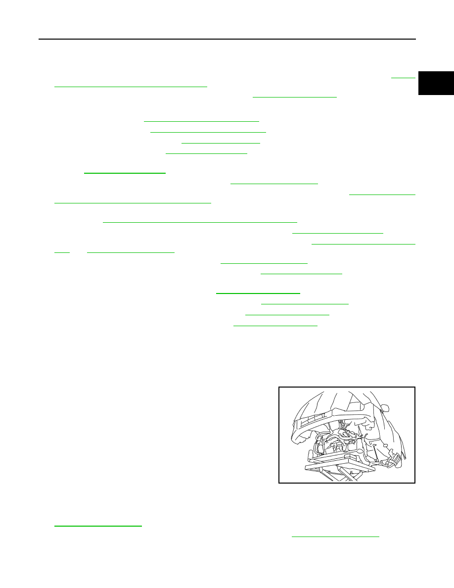
1.
Use a manual lift table caddy (commercial service tool) or equiv-
alently rigid tool such as a transmission jack. Securely support
bottom of front suspension member.
CAUTION:
Put a piece of wood or something similar as the supporting
surface, secure a completely stable condition.
2.
Remove upper torque rod mounting bolt on the engine side and engine mount insulator (RH) mounting nut
on the engine side.
3.
Remove mounting bolt between transverse link and front suspension member with power tool. Refer to
.
4.
Remove front suspension member mounting nuts and bolts. Refer to
5.
Carefully lower jack, or raise lift to remove the engine and the transaxle assembly and front suspension
member. When performing work, observe the following caution:
CAUTION:
JPBIA4772ZZ