Nissan Quest E52. Manual - part 575


  Index      Nissan     Nissan Quest E52 (2011-2014 year) - Service and Repair Manual


Search            


Content   ..  573  574  575  576   ..


Nissan Quest E52. Manual - part 575


FUEL INJECTOR AND FUEL TUBE

EM-49

< REMOVAL AND INSTALLATION >

[VQ35DE]

C

D

E

F

G

H

I

J

K

L

M

A

EM

N

P

O

8.

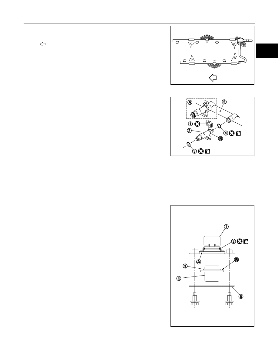
Loosen mounting bolts in the reverse order as shown in the fig-
ure, and remove fuel tube and fuel injector assembly.

CAUTION:

Never tilt fuel tube, or remaining fuel in pipes may flow out
from pipes.

9.

Remove fuel injector from fuel tube as follows:

a.

Open and remove clip (1).

b.

Remove fuel injector (2) from fuel tube (5) by pulling straight.

CAUTION:

• Be careful with remaining fuel that may go out from fuel

tube.

• Be careful not to damage injector nozzle during removal.
• Never bump or drop fuel injector.
• Never disassemble fuel injector.

10. Remove fuel damper from fuel tube.

INSTALLATION

CAUTION:

Do not reuse O-rings.
1.

Install fuel damper as follows:

a.

Install new O-ring (2) to fuel tube (1) as shown. When handling
new O-ring, be careful of the following caution:

CAUTION:

• Do not reuse O-rings.
• Handle O-ring with bare hands. Never wear gloves.
• Lubricate O-ring with new engine oil.
• Never clean O-ring with solvent.
• Check that O-ring and its mating part are free of foreign

material.

• When installing O-ring, be careful not to scratch it with

tool or fingernails. Also be careful not to twist or stretch
O-ring. If O-ring was stretched while it was being
attached, never insert it quickly into fuel tube.

• Insert new O-ring straight into fuel tube. Never twist it.

b.

Install spacer (3) to fuel damper (4).

c.

Insert fuel damper straight into fuel tube.

CAUTION:

• Insert straight, checking that the axis is lined up.
• Never pressure-fit with excessive force.

• Insert fuel damper until (B) is touching (A) of fuel tube.

d.

Tighten bolts evenly in turn.
• After tightening bolts, check that there is no gap between fuel damper cap (5) and fuel tube.

2.

Install new O-rings to fuel injector paying attention to the following.

: Engine front

JPBIA1715ZZ

3

: O-ring (green)

4

: O-ring (black)

A

: Installed condition

B

: Clip mounting groove

JPBIA1958ZZ

Reference value

: 130 N (13.3 kg, 29.2 lb)

JPBIA0316ZZ

EM-50

< REMOVAL AND INSTALLATION >

[VQ35DE]

FUEL INJECTOR AND FUEL TUBE

CAUTION:

• Do not reuse O-rings.
• Upper and lower O-ring are different. Be careful not to confuse them.

• Handle O-ring with bare hands. Never wear gloves.
• Lubricate O-ring with new engine oil.
• Never clean O-ring with solvent.
• Check that O-ring and its mating part are free of foreign material.
• When installing O-ring, be careful not to scratch it with tool or fingernails. Also be careful not to

twist or stretch O-ring. If O-ring was stretched while it was being attached, never insert it quickly
into fuel tube.

• Insert O-ring straight into fuel injector. Never decenter or twist it.

3.

Install fuel injector to fuel tube as follows:

a.

Insert clip (3) into clip mounting groove (F) on fuel injector (5).

• Insert clip so that protrusion (E) of fuel injector matches cutout

(C) of clip.

CAUTION:

• Never reuse clip. Replace it with new one.
• Be careful to keep clip from interfering with O-ring. If

interference occurs, replace O-ring.

b.

Insert fuel injector into fuel tube (1) with clip attached.
• Insert it while matching it to the axial center.
• Insert fuel injector so that protrusion (A) of fuel tube matches

cutout (B) of clip.

• Check that fuel tube flange (G) is securely fixed in flange fixing

groove (D) on clip.

c.

Check that installation is complete by checking that fuel injector
does not rotate or come off.
• Check that protrusions of fuel injectors and fuel tubes are

aligned with cutouts of clips after installation.

4.

Install fuel tube and fuel injector assembly to intake manifold.

CAUTION:

Be careful not to let tip of injector nozzle come in contact with other parts.
• Tighten mounting bolts in two steps in numerical order as

shown in the figure.

5.

Connect fuel injector harness.

6.

Install intake manifold collector. Refer to 

EM-28, "Exploded View"

.

7.

Connect quick connector between fuel feed hose and fuel tube connection with the following procedure:

Fuel tube side

: Black

Nozzle side

: Green

2

: O-ring (black)

4

: O-ring (green)

JPBIA1959ZZ

: Engine front

 1st step

: 10.1 N·m (1.0 kg-m, 7 ft-lb)

 2nd step

: 22.0 N·m (2.2 kg-m, 16 ft-lb)

JPBIA1715ZZ

FUEL INJECTOR AND FUEL TUBE

EM-51

< REMOVAL AND INSTALLATION >

[VQ35DE]

C

D

E

F

G

H

I

J

K

L

M

A

EM

N

P

O

a.

Check no foreign substances are deposited in and around fuel tube and quick connector, and no damage
on them.

b.

Thinly apply new engine oil around fuel tube from tip end to spool end.

c.

Align center to insert quick connector straightly into fuel tube.
• Insert quick connector (1) to fuel tube until top spool (2) is

completely inside quick connector, and 2nd level spool (3)
exposes right below quick connector.

CAUTION:

• Hold (A) position as shown in the figure when inserting

fuel tube into quick connector.

• Carefully align center to avoid inclined insertion to pre-

vent damage to O-ring inside quick connector.

• Insert until you hear a “click” sound and actually feel the engagement.
• To avoid misidentification of engagement with a similar sound, be sure to perform the next step.

d.

Pull quick connector by hand holding position. Check it is completely engaged (connected) so that it does
not come out from fuel tube.

e.

Install quick connector cap (3) to quick connector.

• Install quick connector cap with arrow (A) on surface facing in

direction of quick connector (fuel feed hose side).

CAUTION:

If quick connector cap cannot be installed smoothly, quick
connector may have not been installed correctly. Check
connection again.

f.

Secure fuel feed hose to clamp of quick connector cap.

8.

Install in the reverse order of removal after this step.

Inspection

INFOID:0000000009652779

INSPECTION AFTER INSTALLATION

Check on Fuel Leakage

1.

Turn ignition switch “ON” (with the engine stopped). With fuel pressure applied to fuel piping, check there
are no fuel leakage at connection points.
NOTE:
Use mirrors for checking at points out of clear sight.

2.

Start the engine. With engine speed increased, check again that there are no fuel leakage at connection
points.

CAUTION:

Never touch the engine immediately after stopped, as the engine becomes extremely hot.

B

: Fitted condition

: Upright insertion

1

: Fuel feed hose

2

: Fuel tube

B

: Upper view

JPBIA0275ZZ

JPBIA0039ZZ

EM-52

< REMOVAL AND INSTALLATION >

[VQ35DE]

IGNITION COIL, SPARK PLUG AND ROCKER COVER

IGNITION COIL, SPARK PLUG AND ROCKER COVER

Exploded View

INFOID:0000000009652780

Removal and Installation

INFOID:0000000009652781

REMOVAL

1.

Remove the following parts:

1.

Ignition coil

2.

Spark plug

3.

PCV hose

4.

Clamp

5.

PCV valve

6.

O-ring

7.

Rocker cover (bank 1)

8.

PCV hose

9.

Rocker cover gasket (bank 1)

10.

O-ring

11.

Camshaft position sensor (PHASE) 
(bank 1)

12. Oil filler cap

13.

Rocker cover (bank 2)

14.

Rocker cover gasket (bank 2)

15.

Camshaft position sensor (PHASE) 
(bank 2)

16.

PCV hose

17.

Clamp

A.

To intake manifold collector

B.

Comply with the assembly procedure 
when tightening. Refer to 

EM-52

C.

Camshaft bracket side

D.

To air duct assembly

 : Always replace after every disassembly.

 : N·m (kg-m, ft-lb)

 : N·m (kg-m, in-lb)

 : Should be lubricated with oil.

 : Sealing point

JPBIA1637GB


Content   ..  573  574  575  576   ..