Nissan Quest E52. Manual - part 576


  Index      Nissan     Nissan Quest E52 (2011-2014 year) - Service and Repair Manual


Search            


Content   ..  574  575  576  577   ..


Nissan Quest E52. Manual - part 576


IGNITION COIL, SPARK PLUG AND ROCKER COVER

EM-53

< REMOVAL AND INSTALLATION >

[VQ35DE]

C

D

E

F

G

H

I

J

K

L

M

A

EM

N

P

O

• Engine cover: Refer to 

EM-24, "Exploded View"

.

• Air cleaner cases (upper and lower) and air duct assembly: Refer to 

EM-26, "Exploded View"

.

• Intake manifold collector: Refer to 

EM-28, "Exploded View"

.

2.

Disconnect PCV hose from rocker cover.

3.

Remove camshaft position sensor (PHASE) (bank 1 and bank
2).

CAUTION:

• Handle carefully to avoid dropping and shocks.
• Never disassemble
• Never allow metal powder to adhere to magnetic part at

sensor tip. 

• Never place sensors in a location where they are exposed

to magnetism.

4.

Remove PCV valve and O-ring from rocker cover, if necessary.

5.

Remove oil filler cap from rocker cover, if necessary. 

6.

Remove ignition coil.

CAUTION:

Never shock ignition coil.

7.

Remove harness clips on the rocker cover.
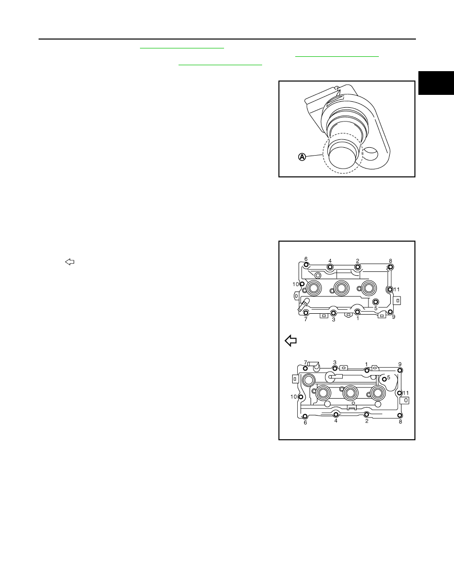
8.

Loosen bolts in the reverse order shown in the figure.

9.

Remove rocker cover gasket from rocker cover.

10. Use scraper to remove all traces of liquid gasket from cylinder head and camshaft bracket (No. 1).

CAUTION:

Never scratch or damage the mating surface when cleaning off old liquid gasket.

INSTALLATION

CAUTION:

Do not reuse O-rings.

A

: Keep off any magnetic materials

: Engine front

JPBIA0454ZZ

JPBIA1634ZZ

EM-54

< REMOVAL AND INSTALLATION >

[VQ35DE]

IGNITION COIL, SPARK PLUG AND ROCKER COVER

1.

Apply liquid gasket to the position shown in the figure with the
following procedure:

Use Genuine RTV silicone sealant or equivalent. Refer to

GI-

22, "Recommended Chemical Products and Sealants"

.

a.

Refer to figure (E) to apply liquid gasket to joint part of camshaft
bracket (No. 1) (1) and cylinder head.

b.

Refer to figure (H) to apply liquid gasket in 90 degrees to figure.

2.

Install rocker cover gasket to rocker cover.

3.

Install rocker cover.
• Check if rocker cover gasket is not dropped from the installation groove of rocker cover. 

4.

Tighten bolts in two steps separately in numerical order as
shown in the figure.

5.

Install in the reverse order of removal after this step. 

A

: Liquid gasket application point

F

:  View  F

I

: End surface of camshaft bracket (No. 1)

b

: 4 mm (0.16 in)

c

φ

2.5 - 3.5 mm (0.098 - 0.138 in)

d

: 5 mm (0.20 in)

g

: 10 mm (0.39 in)

: Engine front

JPBIA0274ZZ

: Engine front

 1st step

: 1.96 N·m (0.20 kg-m, 17 in-lb)

 2nd step

: 8.33 N·m (0.85 kg-m, 74 in-lb)

JPBIA1634ZZ

ENGINE ASSEMBLY

EM-55

< UNIT REMOVAL AND INSTALLATION >

[VQ35DE]

C

D

E

F

G

H

I

J

K

L

M

A

EM

N

P

O

UNIT REMOVAL AND INSTALLATION

ENGINE ASSEMBLY

Exploded View

INFOID:0000000009652782

1.

Upper torque rod

2.

Engine mounting insulator (RH)

3.

Engine mounting bracket (RH)

4.

Engine mounting bracket (front)

5.

Engine mounting insulator (front)

6.

Vacuum hose

7.

Vacuum tube (front)

8.

Vacuum hose

9.

Engine mounting insulator (LH)

10.

Vacuum hose

11. Engine mounting insulator (rear)

12. Engine mounting stay (rear)

13.

Engine mounting bracket (rear)

14. Gusset

15. Rear vacuum tube (lower)

16.

Vacuum hose

17. Rear vacuum tube (upper)

18. Rear torque rod

19.

Rear torque rod bracket

20. Washer

A.

To electronic controlled engine mount 
control solenoid valve

B.

To transaxle

: Vehicle front

 : Always replace after every disassembly.

 : N·m (kg-m, ft-lb)

 : N·m (kg-m, in-lb)

JPBIA4773GB

EM-56

< UNIT REMOVAL AND INSTALLATION >

[VQ35DE]

ENGINE ASSEMBLY

Removal and Installation

INFOID:0000000009652783

WARNING:

• Situate the vehicle on a flat and solid surface.
• Place chocks at front and back of rear wheels.
• For engines not equipped with engine slingers, attach proper slingers and bolts described in PARTS

CATALOG.

CAUTION:

• Always be careful to work safely, avoid forceful or uninstructed operations.
• Never start working until exhaust system and engine coolant are cool enough.
• If items or work required are not covered by the engine section, refer to the applicable sections.
• Always use the support point specified for lifting.
• Use either 2-pole lift type or separate type lift as best you can. If board-on type is used for unavoid-

able reasons, support at the rear axle jacking point with transmission jack or similar tool before
starting work, in preparation for the backward shift of center of gravity.

• For supporting points for lifting and jacking point at rear axle, refer to 

GI-29, "Garage Jack and

Safety Stand and 2-Pole Lift"

.

NOTE:
When removing components such as hoses, tubes/lines, etc., cap or plug openings to prevent fluid from spill-
ing.

REMOVAL

Outline

At first, remove the engine and the transaxle assembly with front suspension member downward. Then sepa-
rate the engine and the transaxle.

Preparation

1.

Release fuel pressure. Refer to 

EC-141, "Work Procedure"

.

2.

Drain engine coolant. Refer to 

CO-8, "Draining"

.

CAUTION:

• Perform this step when the engine is cold.
• Never spill engine coolant on drive belt.

3.

Remove the following parts:
• Engine cover: Refer to 

EM-24, "Removal and Installation"

.

• Engine under cover.
• Front road wheel and tires
• Splash guards (RH and LH): Refer to 

EXT-23, "Exploded View"

.

• Air duct (inlet), air cleaner cases (upper and lower) with mass air flow sensor and air duct assembly:

Refer to 

EM-26, "Exploded View"

.

• Battery and battery tray: Refer to 

PG-105, "Exploded View"

.

• Reservoir tank of radiator: Refer to 

CO-13, "Removal and Installation"

.

• Front wiper arm and extension cowl top: Refer to 

EXT-21, "Exploded View"

.

4.

Disconnect engine room harness at the TCM, ECM, and other sides.

CAUTION:

To keep clean harness connector and avoid damage and foreign materials, cover them completely
with plastic bags or something similar.

5.

Remove battery bracket with ECM and TCM.

Engine Room

1.

Disconnect heater hoses at engine side. Refer to 

CO-26, "Exploded View"

.

• Install plug to avoid leakage of engine coolant.

2.

Remove EVAP hose. Refer to 

EM-28, "Exploded View"

.

3.

Remove fuel feed hose at engine side. Refer to 

EM-47, "Exploded View"

.

• Install plug to avoid leakage of fuel.

4.

Disconnect transaxle shift control cable from transaxle. Refer to 

TM-156, "Removal and Installation"

.

5.

Disconnect brake booster vacuum hose. Refer to 

EM-28, "Exploded View"

.

6.

Remove radiator hose (upper and lower) at engine side. Refer to 

CO-13, "Removal and Installation"

.

7.

Remove return hose and high pressure piping from the power steering oil pump assembly.


Content   ..  574  575  576  577   ..