Nissan Quest E52. Manual - part 571
EXHAUST MANIFOLD AND THREE WAY CATALYST
EM-33
< REMOVAL AND INSTALLATION >
[VQ35DE]
C
D
E
F
G
H
I
J
K
L
M
A
EM
N
P
O
EXHAUST MANIFOLD AND THREE WAY CATALYST
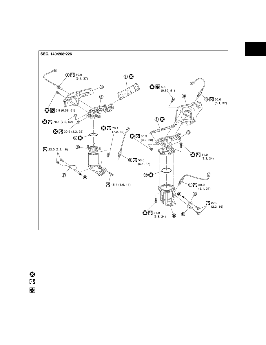
Exploded View
INFOID:0000000009652768
Removal and Installation
INFOID:0000000009652769
REMOVAL
WARNING:
Perform the work when the exhaust and cooling system have completely cooled down.
1.
Gasket
2.
Exhaust manifold (bank 1)
3.
Exhaust manifold cover (bank 1)
4.
Air fuel ratio sensor 1 (bank 1)
5.
Ring gasket
6.
Three way catalyst (bank 1)
7.
Three way catalyst support (bank 1)
8.
Heated oxygen sensor 2 (bank 1)
9.
Three way catalyst (bank 2)
10. Three way catalyst support (bank 2)
11. Heated oxygen sensor 2 (bank 2)
12.
Ring gasket
13. Exhaust manifold (bank 2)
14. Exhaust manifold cover (bank 2)
15.
Air fuel ratio sensor 1 (bank 2)
A.
To oil pan (upper)
B.
Upper mark
: Always replace after every disassembly.
: N·m (kg-m, ft-lb)
: N·m (kg-m, in-lb)
JPBIA4635GB