Nissan Quest E52. Manual - part 569
DRIVE BELT AUTO-TENSIONER
EM-25
< REMOVAL AND INSTALLATION >
[VQ35DE]
C
D
E
F
G
H
I
J
K
L
M
A
EM
N
P
O
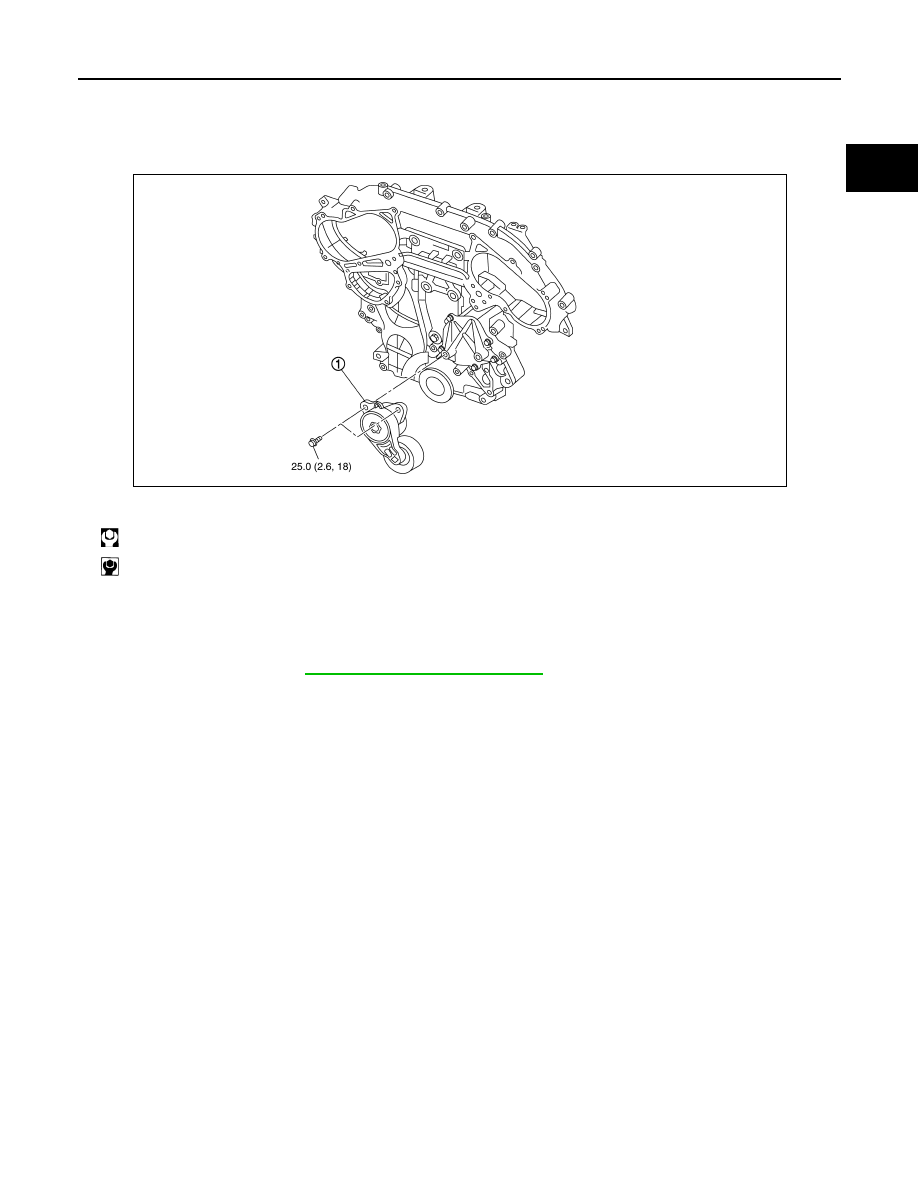
DRIVE BELT AUTO-TENSIONER
Exploded View
INFOID:0000000009652758
Removal and Installation
INFOID:0000000009652759
Removal
1.
Remove drive belt. Refer to
EM-13, "Removal and Installation"
.
2.
Remove auto-tensioner.
Installation
Install in the reverse order of removal.
CAUTION:
If there is damage greater than peeled paint, replace drive belt auto-tensioner.
1.
Drive belt auto-tensioner
: N·m (kg-m, ft-lb)
: N·m (kg-m, in-lb)
JSBIA2874GB