Nissan Quest E52. Manual - part 570


  Index      Nissan     Nissan Quest E52 (2011-2014 year) - Service and Repair Manual


Search            


Content   ..  568  569  570  571   ..


Nissan Quest E52. Manual - part 570


INTAKE MANIFOLD COLLECTOR

EM-29

< REMOVAL AND INSTALLATION >

[VQ35DE]

C

D

E

F

G

H

I

J

K

L

M

A

EM

N

P

O

Removal and Installation

INFOID:0000000009652764

REMOVAL

WARNING:

To avoid the danger of being scalded, never drain engine coolant when the engine is hot.

1.

Remove engine cover. Refer to 

EM-24, "Exploded View"

.

CAUTION:

Be careful not to damage or scratch engine cover.

2.

Remove air cleaner cases (upper and lower) with mass air flow sensor and air duct assembly. Refer to

EM-26, "Exploded View"

.

3.

Prevent engine coolant leakage by draining engine coolant or attaching plug after disconnecting water
hoses. Refer to 

CO-8, "Draining"

.

CAUTION:

Perform this step when the engine is cold.
NOTE:
The above step is not required when removing only intake manifold collector.

4.

Remove electric throttle control actuator as follows:
NOTE:
Water hose is not required to be disconnected when removing only intake manifold collector.
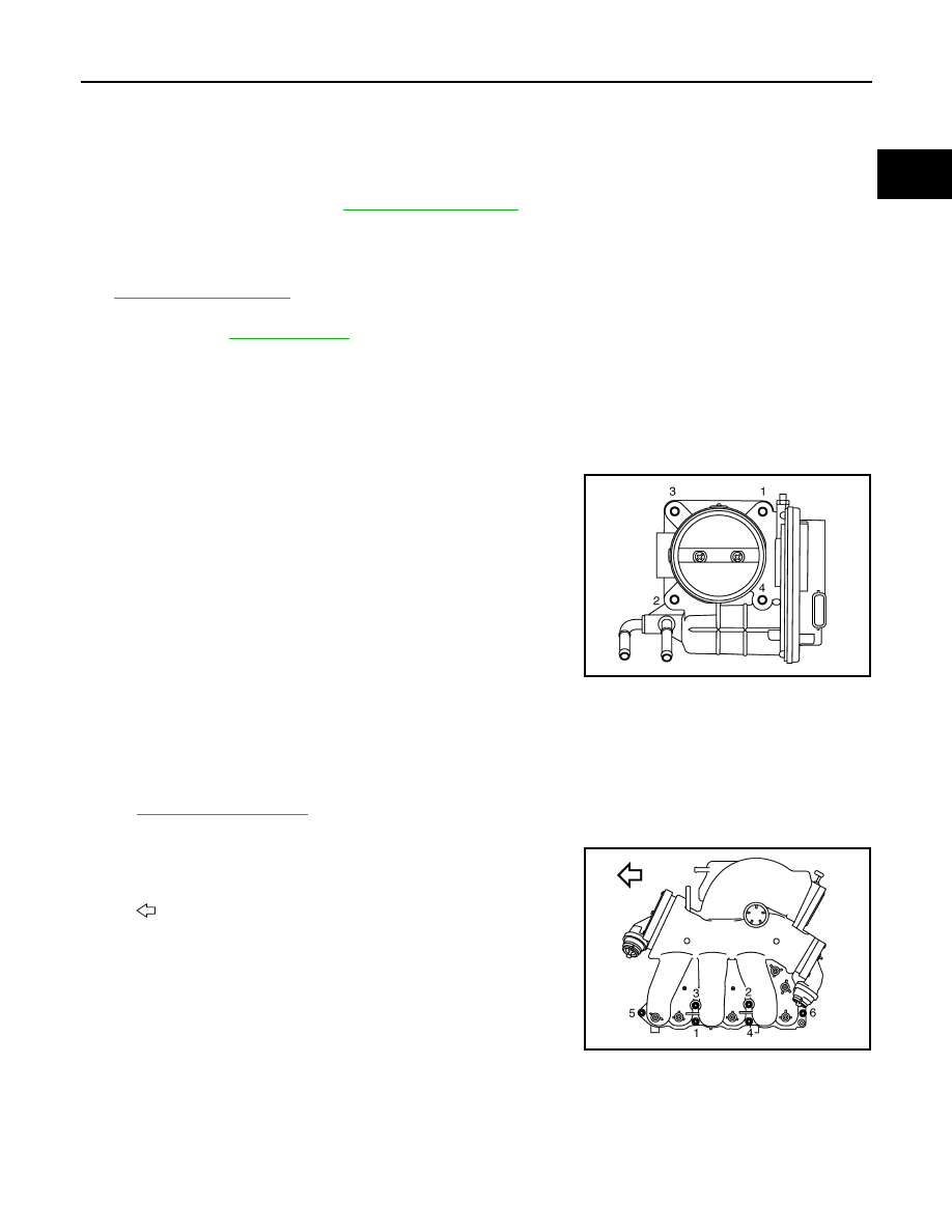
• Loosen mounting bolts in the reverse order as shown in the

figure to remove.

CAUTION:

• Handle carefully to avoid any shock to electric throttle

control actuator.

• Never disassemble.

5.

Remove the following parts:
• Vacuum hose
• PCV hose
• Electronic controlled engine mount control solenoid valve

6.

Remove power steering hose located on the high pressure side from the rear of intake manifold collec-
tor.

ST-35, "Exploded View"

7.

Disconnect EVAP hoses and harness connector from EVAP canister purge volume control solenoid valve.

8.

Loosen mounting nuts and bolts in the reverse order as shown
in the figure, and remove intake manifold collector and gasket.

CAUTION:

Cover engine openings to avoid entry of foreign materials.

INSTALLATION

Note the following, and install in the reverse order of removal.

Intake Manifold Collector

JPBIA1631ZZ

: Engine front

JPBIA1628ZZ

EM-30

< REMOVAL AND INSTALLATION >

[VQ35DE]

INTAKE MANIFOLD COLLECTOR

Tighten mounting nuts and bolts in numerical order as shown in the
figure.

Electric Throttle Control Actuator

• Tighten mounting bolts in numerical order as shown in the figure.
• Perform the “Throttle Valve Closed Position Learning” when har-

ness connector of electric throttle control actuator is disconnected.
Refer to 

EC-136, "Description"

.

• Perform the “Idle Air Volume Learning” and “Throttle Valve Closed

Position Learning” when electric throttle control actuator is
replaced. Refer to 

EC-137, "Description"

.

: Engine front

JPBIA1628ZZ

JPBIA1631ZZ

INTAKE MANIFOLD

EM-31

< REMOVAL AND INSTALLATION >

[VQ35DE]

C

D

E

F

G

H

I

J

K

L

M

A

EM

N

P

O

INTAKE MANIFOLD

Exploded View

INFOID:0000000009652765

Removal and Installation

INFOID:0000000009652766

REMOVAL

1.

Release fuel pressure. Refer to 

EC-141, "Work Procedure"

.

2.

Remove intake manifold collector. Refer to 

EM-29, "Removal and Installation"

.

3.

Remove fuel tube and fuel injector assembly. Refer to 

EM-47, "Exploded View"

.

4.

Loosen mounting nuts and bolts in the reverse order as shown
in the figure to remove intake manifold with power tool.

CAUTION:

• Put identification marks on the intake manifold and cylin-

der head with paint for installing in the right direction.

• Cover the opening with tape to prevent the entry of for-

eign matter into the engine.

5.

Remove gaskets.

CAUTION:

Cover engine openings to avoid entry of foreign materials.

INSTALLATION

Note the following, and install in the reverse order or removal.

Intake Manifold

• If stud bolts were removed, install them and tighten to the specified torque below.

1.

Intake manifold

2.

Gasket

A.

Comply with the assembly procedure 
when tightening. Refer to 

EM-31

 : Always replace after every disassembly.

: N·m (kg-m, ft-lb)

JPBIA1629GB

: Engine front

JPBIA1630ZZ

EM-32

< REMOVAL AND INSTALLATION >

[VQ35DE]

INTAKE MANIFOLD

• Tighten all mounting nuts and bolts to the specified torque in two or

more steps in numerical order shown in the figure.

CAUTION:

Install manifold, according to the marks put on the intake
manifold and cylinder head.

Inspection

INFOID:0000000009652767

INSPECTION AFTER REMOVAL

Surface Distortion

• Check the surface distortion of the intake manifold mating surface

with a straightedge (A) and a feeler gauge (B).

• If it exceeds the limit, replace intake manifold.

: 10.8 N·m (1.1 kg-m, 8 ft-lb)

: Engine front

 1st step

: 7.4 N·m (0.75 kg-m, 5 ft-lb)

 2nd step and after

: 25.5 N·m (2.6 kg-m, 19 ft-lb)

JPBIA1630ZZ

Limit

: Refer to 

EM-129, "Intake Manifold"

.

JPBIA0015ZZ


Content   ..  568  569  570  571   ..