Nissan Quest E52. Manual - part 572


  Index      Nissan     Nissan Quest E52 (2011-2014 year) - Service and Repair Manual


Search            


Content   ..  570  571  572  573   ..


Nissan Quest E52. Manual - part 572


EXHAUST MANIFOLD AND THREE WAY CATALYST

EM-37

< REMOVAL AND INSTALLATION >

[VQ35DE]

C

D

E

F

G

H

I

J

K

L

M

A

EM

N

P

O

• Prevent rust preventives from adhering to the sensor body.

Inspection

INFOID:0000000009652770

INSPECTION AFTER REMOVAL
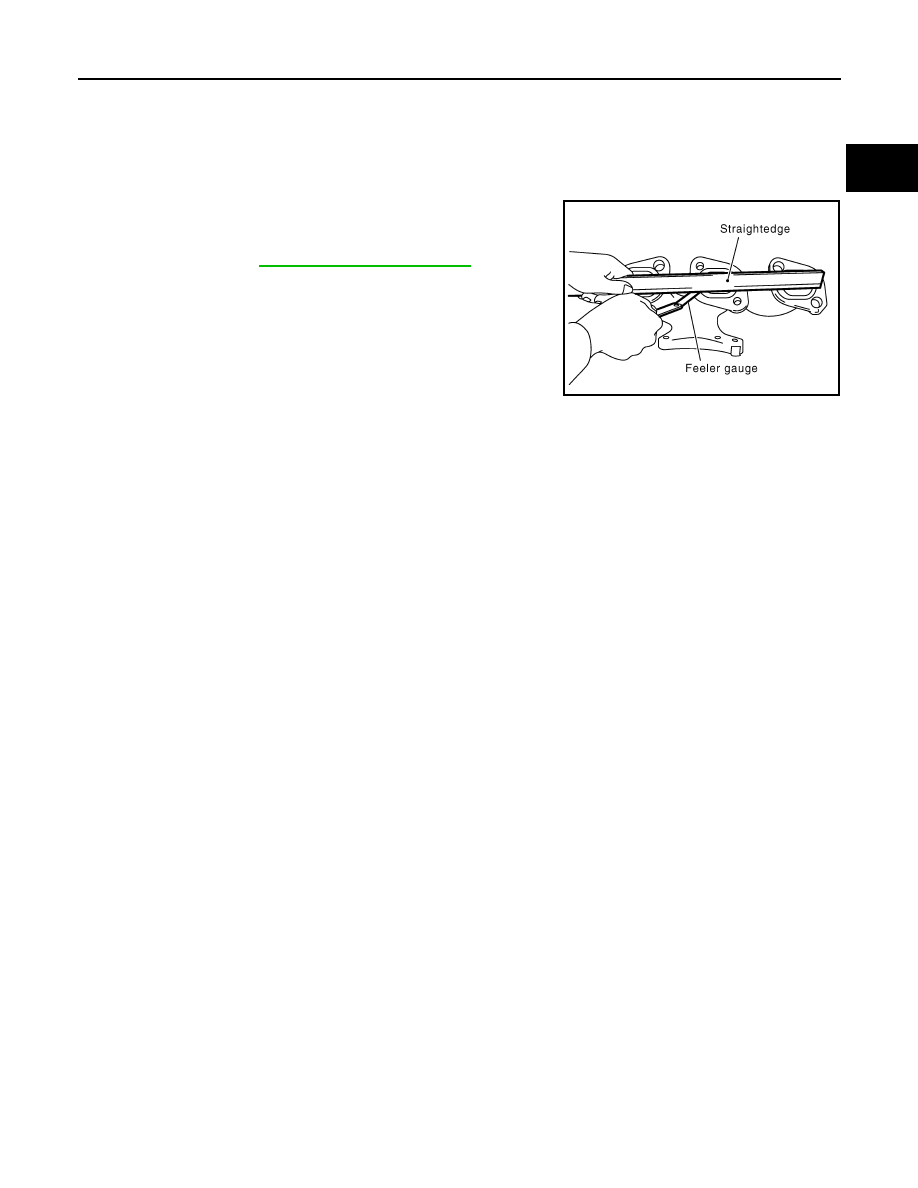
Surface Distortion

• Check the surface distortion of the exhaust manifold mating sur-

face with a straightedge and a feeler gauge.

• If it exceeds the limit, replace exhaust manifold.

Limit

: Refer to 

EM-129, "Exhaust Manifold"

.

PBIC1173E

EM-38

< REMOVAL AND INSTALLATION >

[VQ35DE]

OIL PAN AND OIL STRAINER

OIL PAN AND OIL STRAINER

Exploded View

INFOID:0000000009652771

Removal and Installation

INFOID:0000000009652772

REMOVAL

CAUTION:

To avoid the danger of being scalded, never drain engine oil when the engine is hot.
NOTE:
When removing oil pan (lower) or oil strainer only, take step 1 then step 32 and 33.

1.

Drain engine oil. Refer to 

LU-9, "Draining"

.

CAUTION:

Never spill engine oil on drive belt.

1.

Oil pan (upper)

2.

O-ring

3.

Oil pan gasket (front)

4.

Relief valve

5.

Oil pressure switch

6.

Oil cooler

7.

Connector bolt

8.

Oil filter

9.

Oil strainer

10. Drain plug

11.

Drain plug washer

12. Oil pan (lower)

13. Rear plate cover

14. Crankshaft position sensor (POS)

15. Oil pan gasket (rear)

A.

Comply with the assembly procedure 
when tightening. Refer to 

LU-11

B.

To oil pump

C.

Oil pan side

 : Always replace after every disassembly.

 : N·m (kg-m, ft-lb)

 : N·m (kg-m, in-lb)

 : Sealing point

JPBIA1636GB

OIL PAN AND OIL STRAINER

EM-39

< REMOVAL AND INSTALLATION >

[VQ35DE]

C

D

E

F

G

H

I

J

K

L

M

A

EM

N

P

O

2.

Drain engine coolant. Refer to 

CO-8, "Draining"

.

CAUTION:

Never spill engine coolant on drive belt.

3.

Remove following parts:
• Front road wheel and tires (RH and LH).
• Splash guard (RH and LH): Refer to 

EXT-23, "Exploded View"

.

• Exhaust front tube: Refer to 

EX-5, "Exploded View"

.

• Drive belt: Refer to 

EM-13, "Removal and Installation"

.

• Engine under cover.
• Crankshaft position sensor.

4.

Remove A/C compressor with piping connected, and temporarily secure it to aside. Refer to 

HA-31,

"COMPRESSOR : Removal and Installation"

.

5.

Remove oil level gauge. Refer to 

EM-93, "Exploded View"

.

6.

Remove air duct (inlet). Refer to

EM-26, "Removal and Installation"

.

7.

Remove extension cowl top. Refer to 

EXT-22, "Removal and Installation"

.

8.

Remove high pressure side piping from intake manifold collector. Refer to 

EM-28, "Exploded View"

.

9.

Remove heater tube bracket (front). Refer to 

HA-47, "Exploded View"

.

10. Remove vacuum hose from engine mounting (front and rear). Refer to 

EM-55, "Exploded View"

.

11. Remove front drive shaft (RH). Refer to 

FAX-19, "RIGHT SIDE : Removal and Installation"

.

12. Remove heat insulator. Refer to 

ST-13, "Exploded View"

.

13. Remove steering lower joint. Refer to 

ST-16, "Exploded View"

.

14. Remove three way catalyst (bank 1 and bank 2). Refer to 

EM-33, "Removal and Installation"

15. Remove oil pressure switch.

16. Remove oil filter. Refer to 

LU-11, "Removal and Installation"

.

17. Remove engine mounting insulator (front and rear) fixing nuts. Refer to 

EM-55, "Exploded View"

.

18. Remove front drive shaft (LH) from transaxle. Refer to 

FAX-18, "LEFT SIDE : Removal and Installation"

.

19. Remove CVT fluid cooler hose from front suspension member.
20. Remove the connector of auto levelizer control unit and clip.

21. Remove the mounting nuts of stabilizer connecting rod upper side. Refer to 

FSU-15, "Exploded View"

.

22. Remove power steering return hose and power steering return tube from front suspension member. Refer

to 

ST-35, "Exploded View"

.

23. Support transaxle assembly with a suitable jack.

CAUTION:

When setting the transmission jack, be careful not to allow it to collide against the drain plug.

24. Remove engine mounting insulator (LH) mounting bolts from front suspension member. Refer to 

EM-55,

"Exploded View"

.

25. Remove rear torque rod and rear torque rod bracket. Refer to 

EM-56, "Removal and Installation"

.

26. Support front suspension member assembly with a suitable jack.

27. Remove member stay, front suspension member fixing bolts and bolts. Refer to 

FSU-17, "Exploded View"

.

28. Lower the jack on the front suspension side to the height where the hose of power steering is not

stretched taut.

29. Remove support bearing bracket. Refer to 

FAX-17, "Exploded View"

30. Remove oil cooler and water pipe. Refer to

LU-12, "Exploded View"

.

31. Remove oil pan (lower) as follows:

EM-40

< REMOVAL AND INSTALLATION >

[VQ35DE]

OIL PAN AND OIL STRAINER

a.

Loosen mounting bolts in the reverse order as shown in the fig-
ure to remove.

b.

Insert the seal cutter [SST: KV10111100 (J-37228)] (A) between
oil pan (upper) and oil pan (lower).

CAUTION:

• Be careful not to damage the mating surfaces.
• Never insert a screwdriver, this will damage the mating

surfaces.

c.

Slide the seal cutter by tapping on the side of tool with a ham-
mer. Remove oil pan (lower).

32. Remove oil strainer.

33. Loosen mounting bolts in the reverse order as shown in the fig-

ure to remove.
• Insert the seal cutter [SST: KV10111100 (J-37228)] between

oil pan (upper) and cylinder block. Slide seal cutter by tapping
on the side of tool with a hammer. Remove oil pan (upper).

CAUTION:

• Be careful not to damage the mating surfaces.
• Never insert a screwdriver, this will damage the mating

surfaces.

34. Remove O-rings (2) from bottom of cylinder block (1) and oil

pump (3).

PBIC0782E

JPBIA0276ZZ

PBIC1636E

: Engine front

JPBIA1379ZZ


Content   ..  570  571  572  573   ..