Nissan Quest E52. Manual - part 469
EC-86
< ECU DIAGNOSIS INFORMATION >
[VQ35DE]
ECM
33
(R/B)
128
(B)
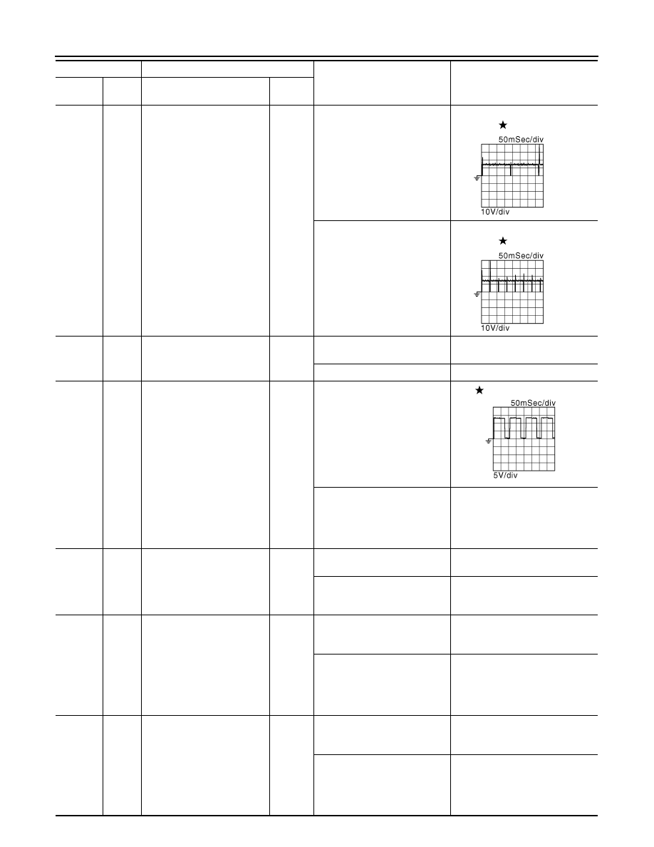
Fuel injector No. 1
Output
[Engine is running]
• Warm-up condition
• Idle speed
NOTE:
The pulse cycle changes de-
pending on rpm at idle
BATTERY VOLTAGE
(11 - 14 V)
44
(R/W)
Fuel injector No. 2
45
(P/B)
Fuel injector No. 6
46
(L/W)
Fuel injector No. 5
[Engine is running]
• Warm-up condition
• Engine speed: 2,000 rpm
BATTERY VOLTAGE
(11 - 14 V)
47
(LG/R)
Fuel injector No. 4
48
(R/Y)
Fuel injector No. 3
34
(O)
128
(B)
Throttle control motor relay
Output
[Ignition switch: ON
→
OFF]
0 - 1.0 V
→
BATTERY VOLTAGE
(11 - 14 V)
→
0 V
[Ignition switch: ON]
0 - 1.0 V
37
(P/B)
128
(B)
Heated oxygen sensor 2 heat-
er (bank 1)
Output
[Engine is running]
• Engine speed: Below 3,600
rpm after the following condi-
tions are met
- Engine: after warming up
- Keeping the engine speed be-
tween 3,500 and 4,000 rpm
for 1 minute and at idle for 1
minute under no load
10 V
[Ignition switch: ON]
• Engine stopped
[Engine is running]
• Engine speed: Above 3,600
rpm
BATTERY VOLTAGE
(11 - 14 V)
38
(BR/W)
128
(B)
Electronic controlled engine
mount control solenoid valve
Output
[Engine is running]
• Idle speed
0 - 1.0 V
[Engine is running]
• Engine speed: More than 950
rpm
BATTERY VOLTAGE
(11 - 14 V)
39
(V)
128
(B)
VIAS control solenoid valve 1
Output
[Engine is running]
• Warm-up condition
• Idle speed
BATTERY VOLTAGE
(11 - 14 V)
[Engine is running]
• Warm-up condition
• When revving engine up to
5,000 rpm quickly
BATTERY VOLTAGE (11 - 14 V)
↓
0 - 1.0 V
↓
BATTERY VOLTAGE (11 - 14 V)
40
(GR/B)
128
(B)
VIAS control solenoid valve 2
Output
[Engine is running]
• Warm-up condition
• Idle speed
BATTERY VOLTAGE
(11 - 14 V)
[Engine is running]
• Warm-up condition
• When revving engine up to
5,000 rpm quickly
BATTERY VOLTAGE (11 - 14 V)
↓
0 - 1.0 V
↓
BATTERY VOLTAGE (11 - 14 V)
Terminal No.
Description
Condition
Value
(Approx.)
+
-–
Signal name
Input/
Output
JMBIA0047GB
JMBIA0048GB
JMBIA0902GB