Nissan Quest E52. Manual - part 470


  Index      Nissan     Nissan Quest E52 (2011-2014 year) - Service and Repair Manual


Search            


Content   ..  468  469  470  471   ..


Nissan Quest E52. Manual - part 470


EC-90

< ECU DIAGNOSIS INFORMATION >

[VQ35DE]

ECM

89

(W/B)

84

(Y/B)

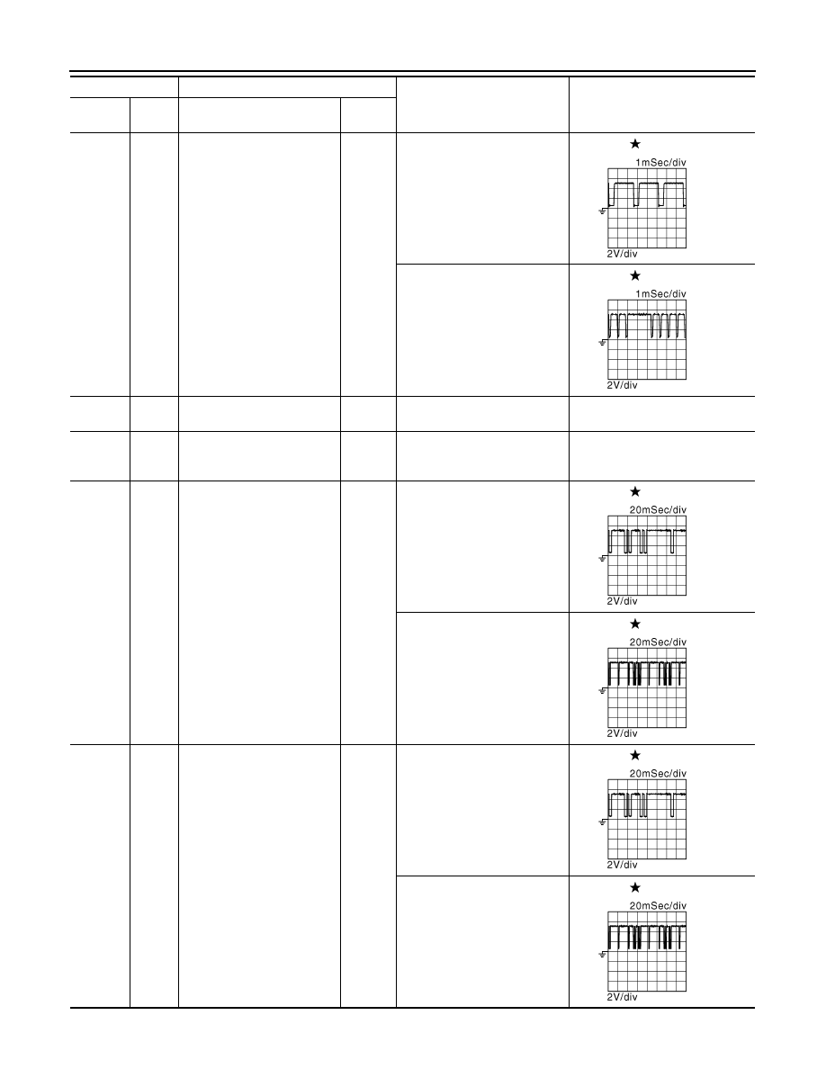
Crankshaft position sensor 
(POS)

Input

[Engine is running]
• Warm-up condition
• Idle speed

NOTE:
The pulse cycle changes de-
pending on rpm at idle

4.0 - 5.0 V

[Engine is running]
• Engine speed: 2,000 rpm

4.0 - 5.0 V

91

(—)

Sensor ground
(Knock sensor)

92

(Y/G)

Sensor ground
[Camshaft position sensor 
(PHASE) (bank 2)]

93

(BR/W)

92

(Y/G)

Camshaft position sensor 
(PHASE) (bank 2)

Input

[Engine is running]
• Warm-up condition
• Idle speed

NOTE:
The pulse cycle changes de-
pending on rpm at idle

3.0 - 5.0 V

[Engine is running]
• Engine speed is 2,000 rpm

3.0 - 5.0 V

94

(W/R)

88

(B/R)

Camshaft position sensor 
(PHASE) (bank 1)

Input

[Engine is running]
• Warm-up condition
• Idle speed

NOTE:
The pulse cycle changes de-
pending on rpm at idle

3.0 - 5.0 V

[Engine is running]
• Engine speed is 2,000 rpm

3.0 - 5.0 V

Terminal No.

Description

Condition

Value

(Approx.)

+

-–

Signal name

Input/

Output

JMBIA0041GB

JMBIA0042GB

JMBIA0045GB

JMBIA0046GB

JMBIA0045GB

JMBIA0046GB

ECM

EC-91

< ECU DIAGNOSIS INFORMATION >

[VQ35DE]

C

D

E

F

G

H

I

J

K

L

M

A

EC

N

P

O

96

(BR/W)

64

(G)

Sensor power supply
(Refrigerant pressure sensor)

[Ignition switch: ON]

5 V

97

(W)

100

(B)

Accelerator pedal position 
sensor 1

Input

[Ignition switch: ON]
• Engine stopped
• Accelerator pedal: Fully re-

leased

0.5 - 1.0 V

[Ignition switch: ON]
• Engine stopped
• Accelerator pedal: Fully de-

pressed

4.2 - 4.8 V

98

(O)

116

(G)

Accelerator pedal position 
sensor 2

Input

[Ignition switch: ON]
• Engine stopped
• Accelerator pedal: Fully re-

leased

0.25 - 0.50 V

[Ignition switch: ON]
• Engine stopped
• Accelerator pedal: Fully de-

pressed

2.0 - 2.5 V

99

(P)

100

(B)

Sensor power supply
(Accelerator pedal position 
sensor 1)

[Ignition switch: ON]

5 V

100

(B)

Sensor ground
(Accelerator pedal position 
sensor 1)

101

(Y)

108

(BR)

ASCD steering switch

Input

[Ignition switch: ON]
• ASCD steering switch: OFF

4 V

[Ignition switch: ON]
• MAIN switch: Pressed

0 V

[Ignition switch: ON]
• CANCEL switch: Pressed

1 V

[Ignition switch: ON]
• RESUME/ACCELERATE 

switch: Pressed

3 V

[Ignition switch: ON]
• SET/COAST switch: Pressed

2 V

102

(LG)

112

(V)

EVAP control system pres-
sure sensor

Input

[Ignition switch: ON]

1.8 - 4.8 V

103

(GR)

116

(G)

Sensor power supply
(Accelerator pedal position 
sensor 2)

[Ignition switch: ON]

5 V

104

(LG)

Data link connector

Input/

Output

106

(V)

128

(B)

EVAP canister vent control 
valve

Output

[Ignition switch: ON]

BATTERY VOLTAGE
(11 - 14 V)

107
(W)

112

(V)

Sensor power supply
(EVAP control system pres-
sure sensor)

[Ignition switch: ON]

5 V

108

(BR)

Sensor ground
(ASCD steering switch)

109

(G)

128

(B)

Ignition switch

Input

[Ignition switch: OFF]

0 V

[Ignition switch: ON]

BATTERY VOLTAGE
(11 - 14 V)

Terminal No.

Description

Condition

Value

(Approx.)

+

-–

Signal name

Input/

Output

EC-92

< ECU DIAGNOSIS INFORMATION >

[VQ35DE]

ECM

: Average voltage for pulse signal (Actual pulse signal can be confirmed by oscilloscope.)

*1: This may vary depending on internal resistance of the tester.

*2: Before measuring the terminal voltage, confirm that the battery is fully charged. Refer to 

PG-97, "How to Handle Battery"

.

Fail-safe

INFOID:0000000009650985

NON DTC RELATED ITEM

111

(Y)

120

(SB)

Fuel tank temperature sensor

Input

[Engine is running]

0 - 4.8 V
Output voltage varies with fuel tank 
temperature.

112

(V)

Sensor ground
(EVAP control system pres-
sure sensor)

113

(P)

CAN communication line

Input/

Output

114

(L)

CAN communication line

Input/

Output

116

(G)

Sensor ground
(Accelerator pedal position 
sensor 2)

118

(R)

128

(B)

PNP signal

Input

[Ignition switch: ON]
• Selector lever: P or N position

BATTERY VOLTAGE
(11 - 14 V)

[Ignition switch: ON]
• Selector lever: Except above 

position

0 V

120

(SB)

Sensor ground
(Fuel tank temperature sen-
sor)

121

(L)

128

(B)

Power supply for ECM

Input

[Ignition switch: ON]

BATTERY VOLTAGE
(11 - 14 V)

122

(SB)

128

(B)

Stop lamp switch

Input

[Ignition switch: OFF]
• Brake pedal: Fully released

0 V

[Ignition switch: OFF]
• Brake pedal: Slightly de-

pressed

BATTERY VOLTAGE
(11 - 14 V)

123

(B)

124

(B)

ECM ground

126

(BR)

128

(B)

ASCD brake switch

Input

[Ignition switch: ON]
• Brake pedal: Slightly de-

pressed

0 V

[Ignition switch: ON]
• Brake pedal: Fully released

BATTERY VOLTAGE
(11 - 14 V)

127

(B)

128

(B)

ECM ground

Terminal No.

Description

Condition

Value

(Approx.)

+

-–

Signal name

Input/

Output

ECM

EC-93

< ECU DIAGNOSIS INFORMATION >

[VQ35DE]

C

D

E

F

G

H

I

J

K

L

M

A

EC

N

P

O

DTC RELATED ITEM

Engine operating condi-

tion in fail-safe mode

Detected items

Remarks

Reference 

page

Engine speed will not 
rise more than 2,500 rpm 
due to the fuel cut

Malfunction indicator 
lamp circuit

When there is an open circuit on MIL circuit, the ECM cannot warn the 
driver by illuminating MIL when there is malfunction on engine control 
system.
Therefore, when electrical controlled throttle and part of ECM related 
diagnoses are continuously detected as NG for 5 trips, ECM warns the 
driver that engine control system malfunctions and MIL circuit is open 
by means of operating the fail-safe function.
The fail-safe function also operates when above diagnoses except MIL 
circuit are detected and demands the driver to repair the malfunction.

EC-437

DTC No.

Detected items

Engine operating condition in fail-safe mode

P0011

P0021

Intake valve timing control

The signal is not energized to the intake valve timing control solenoid valve and the valve 
control does not function.

P0101
P0102
P0103

Mass air flow sensor circuit

Engine speed will not rise more than 2,400 rpm due to the fuel cut.

P0117
P0118

Engine coolant tempera-
ture sensor circuit

Engine coolant temperature will be determined by ECM based on the following condition.
CONSULT displays the engine coolant temperature decided by ECM.

Condition

Engine coolant temperature decided 

(CONSULT display)

Just as ignition switch is turned ON 
or START

40

°

C (104

°

F)

Approx 4 minutes or more after en-
gine starting

80

°

C (176

°

F)

Except as shown above

40 - 80

°

C (104 - 176

°

F)

(Depends on the time)

When the fail-safe system for engine coolant temperature sensor is activated, the cooling 
fan operates while engine is running.

P0122
P0123
P0222
P0223
P2135

Throttle position sensor

The ECM controls the electric throttle control actuator in regulating the throttle opening in 
order for the idle position to be within +10 degrees.
The ECM regulates the opening speed of the throttle valve to be slower than the normal 
condition.
Therefore, the acceleration will be poor. 

P0196
P0197
P0198

Engine oil temperature 
sensor

Intake valve timing control does not function.

P0500

Vehicle speed sensor

The cooling fan operates (Highest) while engine is running.

P0605

ECM

(When ECM calculation function is malfunctioning:)
ECM stops the electric throttle control actuator control, throttle valve is maintained at a 
fixed opening (approx. 5 degrees) by the return spring.
ECM deactivates ASCD operation.

P0643

Sensor power supply

ECM stops the electric throttle control actuator control, throttle valve is maintained at a 
fixed opening (approx. 5 degrees) by the return spring.

P1805

Brake switch

ECM controls the electric throttle control actuator by regulating the throttle opening to a 
small range.
Therefore, acceleration will be poor.

Vehicle condition

Driving condition

When engine is idling

Normal

When accelerating

Poor acceleration

P2100
P2103

Throttle control motor relay

ECM stops the electric throttle control actuator control, throttle valve is maintained at a 
fixed opening (approx. 5 degrees) by the return spring.


Content   ..  468  469  470  471   ..