Nissan Quest E52. Manual - part 467


  Index      Nissan     Nissan Quest E52 (2011-2014 year) - Service and Repair Manual


Search            


Content   ..  465  466  467  468   ..


Nissan Quest E52. Manual - part 467


EC-78

< SYSTEM DESCRIPTION >

[VQ35DE]

DIAGNOSIS SYSTEM (ECM)

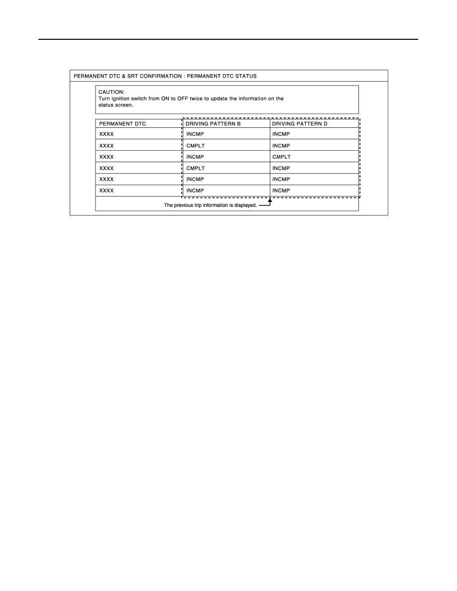
Since the “PERMANENT DTC STATUS” screen displays the previous trip information, repeat the
following twice to update the information: “Ignition switch OFF”, “Wait for more than 10 seconds”
and “Ignition switch ON”.

NOTE:
This mode is not used in regions that permanent DTCs are not regulated by law.

SRT WORK SUPPORT Mode

This mode enables a technician to drive a vehicle to set the SRT while monitoring the SRT status.

PERMANENT DTC WORK SUPPORT Mode

This mode enables a technician to drive a vehicle to complete the driving pattern that is required for erasing
permanent DTC.
NOTE:
This mode is not used in regions that permanent DTCs are not regulated by law.

JSBIA0062GB

ECM

EC-79

< ECU DIAGNOSIS INFORMATION >

[VQ35DE]

C

D

E

F

G

H

I

J

K

L

M

A

EC

N

P

O

ECU DIAGNOSIS INFORMATION

ECM

Reference Value

INFOID:0000000009650984

VALUES ON THE DIAGNOSIS TOOL

NOTE:
• The following table includes information (items) inapplicable to this vehicle. For information (items) applica-

ble to this vehicle, refer to CONSULT display items.

• Numerical values in the following table are reference values.
• These values are input/output values that ECM receives/transmits and may differ from actual operations.
Example: The ignition timing shown by the timing light may differ from the ignition timing displayed on the data
monitor. This occurs because the timing light shows a value calculated by ECM according to signals received
from the cam shaft position sensor and other sensors related to ignition timing.
For outlines of following items, refer to 

EC-69, "CONSULT Function"

.

Monitor Item

Condition

Values/Status

ENG SPEED

Run engine and compare CONSULT value with the tachometer indication.

Almost the same speed as 
the tachometer indication.

MAS A/F SE-B1

See 

EC-155, "Description"

.

B/FUEL SCHDL

See 

EC-155, "Description"

.

A/F ALPHA-B1

See 

EC-155, "Description"

.

A/F ALPHA-B2

See 

EC-155, "Description"

.

COOLANT TEMP/S

• Engine: After warming up

More than 70

°

C (158

°

F)

A/F SEN1 (B1)

• Engine: After warming up

Maintaining engine speed at 2,000 rpm

Fluctuates around 2.2 V

A/F SEN1 (B2)

• Engine: After warming up

Maintaining engine speed at 2,000 rpm

Fluctuates around 2.2 V

HO2S2 (B1)

• Revving engine from idle to 3,000 rpm quickly after the following conditions 

are met.

- Engine: After warming up
- After keeping engine speed between 3,500 and 4,000 rpm for 1 minute and at 

idle for 1 minute under no load

0 - 0.3 V 

←→

 Approx. 0.6 - 

1.0 V

HO2S2 (B2)

• Revving engine from idle to 3,000 rpm quickly after the following conditions 

are met.

- Engine: After warming up
- After keeping engine speed between 3,500 and 4,000 rpm for 1 minute and at 

idle for 1 minute under no load

0 - 0.3 V 

←→

 Approx. 0.6 - 

1.0 V

HO2S2 MNTR (B1)

• Revving engine from idle to 3,000 rpm quickly after the following conditions 

are met.

- Engine: After warming up
- After keeping engine speed between 3,500 and 4,000 rpm for 1 minute and at 

idle for 1 minute under no load

LEAN 

←→

 RICH

HO2S2 MNTR (B2)

• Revving engine from idle to 3,000 rpm quickly after the following conditions 

are met.

- Engine: After warming up
- After keeping engine speed between 3,500 and 4,000 rpm for 1 minute and at 

idle for 1 minute under no load

LEAN 

←→

 RICH

VHCL SPEED SE

• Turn drive wheels and compare CONSULT value with the speedometer indi-

cation.

Almost the same speed as 
speedometer indication

BATTERY VOLT

• Ignition switch: ON (Engine stopped)

11 - 14 V

ACCEL SEN 1

• Ignition switch: ON

(Engine stopped)

Accelerator pedal: Fully released

0.5 - 1.0 V

Accelerator pedal: Fully depressed

4.2 - 4.8 V

ACCEL SEN 2*

1

• Ignition switch: ON

(Engine stopped)

Accelerator pedal: Fully released

0.5 - 1.0 V

Accelerator pedal: Fully depressed

4.2 - 4.8 V

EC-80

< ECU DIAGNOSIS INFORMATION >

[VQ35DE]

ECM

TP SEN 1-B1

• Ignition switch: ON

(Engine stopped)

• Selector lever: D position

Accelerator pedal: Fully released

More than 0.36 V

Accelerator pedal: Fully depressed

Less than 4.75 V

TP SEN 2-B1*

1

• Ignition switch: ON

(Engine stopped)

• Selector lever: D position

Accelerator pedal: Fully released

More than 0.36 V

Accelerator pedal: Fully depressed

Less than 4.75 V

FUEL T/TMP SE

• Ignition switch: ON

Indicates fuel tank tempera-
ture

INT/A TEMP SE

• Ignition switch: ON

Indicates intake air tempera-
ture

EVAP SYS PRES

• Ignition switch: ON

Approx. 1.8 - 4.8 V

FUEL LEVEL SE

• Ignition switch: ON

Depending on fuel level of 
fuel tank

START SIGNAL

• Ignition switch: ON 

 START 

 ON

OFF 

 ON 

 OFF

CLSD THL POS

• Ignition switch: ON

(Engine stopped)

Accelerator pedal: Fully released

ON

Accelerator pedal: Slightly depressed

OFF

AIR COND SIG

• Engine: After warming up, idle the 

engine

Air conditioner switch: OFF

OFF

Air conditioner switch: ON
(Compressor operates.)

ON

P/N POSI SW

• Ignition switch: ON

Selector lever: P or N position

ON

Selector lever: Except above position

OFF

PW/ST SIGNAL

• Engine: After warming up, idle the 

engine

Steering wheel: Not being turned

OFF

Steering wheel: Being turned

ON

LOAD SIGNAL

• Ignition switch: ON

Rear window defogger switch: ON
and/or
Lighting switch: 2nd position

ON

Rear window defogger switch and lighting 
switch: OFF

OFF

IGNITION SW

• Ignition switch: ON 

 OFF 

 ON

ON 

 OFF 

 ON

HEATER FAN SW

• Engine: After warming up, idle the 

engine

Heater fan switch: ON

ON

Heater fan switch: OFF

OFF

BRAKE SW

• Ignition switch: ON

Brake pedal: Fully released

OFF

Brake pedal: Slightly depressed

ON

INJ PULSE-B1

• Engine: After warming up
• Selector lever: P or N position
• Air conditioner switch: OFF
• No  load

Idle

2.0 - 3.0 msec

2,000 rpm

1.9 - 2.9 msec

INJ PULSE-B2

• Engine: After warming up
• Selector lever: P or N position
• Air conditioner switch: OFF
• No  load

Idle

2.0 - 3.0 msec

2,000 rpm

1.9 - 2.9 msec

IGN TIMING

• Engine: After warming up
• Selector lever: P or N position
• Air conditioner switch: OFF
• No  load

Idle

7 - 17

°

BTDC

2,000 rpm

25 - 45

°

BTDC

CAL/LD VALUE

• Engine: After warming up
• Selector lever: P or N position
• Air conditioner switch: OFF
• No  load

Idle

5 - 35%

2,500 rpm

5 - 35%

MASS AIRFLOW

• Engine: After warming up
• Selector lever: P or N position
• Air conditioner switch: OFF
• No  load

Idle

2.0 - 6.0 g/s

2,500 rpm

7.0 - 20.0 g/s

Monitor Item

Condition

Values/Status

ECM

EC-81

< ECU DIAGNOSIS INFORMATION >

[VQ35DE]

C

D

E

F

G

H

I

J

K

L

M

A

EC

N

P

O

PURG VOL C/V

• Engine: After warming up
• Selector lever: P or N position
• Air conditioner switch: OFF
• No  load

Idle
(Accelerator pedal: Not depressed even 
slightly, after engine starting.)

0%

2,000 rpm

INT/V TIM (B1)

• Engine: After warming up
• Selector lever: P or N position
• Air conditioner switch: OFF
• No  load

Idle

5 - 5

°

CA

2,000 rpm

Approx. 0 - 30

°

CA

INT/V TIM (B2)

• Engine: After warming up
• Selector lever: P or N position
• Air conditioner switch: OFF
• No  load

Idle

5 - 5

°

CA

2,000 rpm

Approx. 0 - 30

°

CA

INT/V SOL (B1)

• Engine: After warming up
• Selector lever: P or N position
• Air conditioner switch: OFF
• No  load

Idle

0 - 2%

2,000 rpm

Approx. 0 - 50%

INT/V SOL (B2)

• Engine: After warming up
• Selector lever: P or N position
• Air conditioner switch: OFF
• No  load

Idle

0 - 2%

2,000 rpm

Approx. 0 - 50%

VIAS S/V-1

• Engine: After warming up
• Selector lever: P or N position
• Air conditioner switch: OFF
• No  load

When revving engine up to 5,000 rpm 
quickly

OFF 

ON 

 OFF

VIAS S/V-2

• Engine: After warming up
• Selector lever: P or N position
• Air conditioner switch: OFF
• No  load

When revving engine up to 5,000 rpm 
quickly

OFF 

ON 

 OFF

AIR COND RLY

• Engine: After warming up, idle the 

engine

Air conditioner switch: OFF

OFF

Air conditioner switch: ON
(Compressor operates)

ON

ENGINE MOUNT

• Engine: After warming up

Below 950 rpm

IDLE

Above 950 rpm

TRVL

FUEL PUMP RLY

• For 1 second after turning ignition switch: ON
• Engine running or cranking

ON

• Except above

OFF

VENT CONT/V

• Ignition switch: ON

OFF

THRTL RELAY

• Ignition switch: ON

ON

COOLING FAN

• Engine: After warming up, idle the 

engine

• Air conditioner switch: OFF

Engine coolant temperature: 97

°

(206

°

F) or less

OFF

Engine coolant temperature: Between 
98

°

C (208

°

F) and 99

°

C (210

°

F)

LOW

Engine coolant temperature: Between 
100

°

C (212

°

F) and 104

°

C (219

°

F)

MID

Engine coolant temperature: 105

°

(221

°

F) or more

HI

HO2S2 HTR (B1)

• Engine speed: Below 3,600 rpm after the following conditions are met.
- Engine: After warming up
- Keeping the engine speed between 3,500 and 4,000 rpm for 1 minute and at 

idle for 1 minute under no load

ON

• Engine speed: Above 3,600 rpm

OFF

Monitor Item

Condition

Values/Status


Content   ..  465  466  467  468   ..