Nissan Quest E52. Manual - part 438
DLK-466
< REMOVAL AND INSTALLATION >
SLIDE DOOR LOCK
SLIDE DOOR LOCK
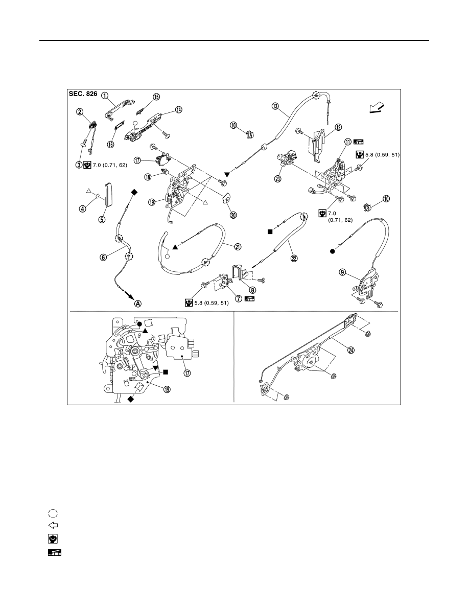
Exploded View
INFOID:0000000009649473
CAUTION:
• Apply anticorrosive agent onto the mounting surface.
1.
Outside handle assembly
2.
Outside handle escutcheon
3.
TORX bolt
4.
Snap pin
5.
Inside handle
6.
Remote control door lock cable
7.
Slide door lock assembly (front)
8.
Slide door lock cover (front)
9.
Slide door lock release actuator
10. Cable clip
11. Slide door lock assembly (rear)
12. Slide door lock cover (rear)
13. Slide door lock cable (rear)
14. Outside handle bracket
15. Rear gasket
16. Front gasket
17. Slide door lock actuator
18. Clip
19. Remote control assembly
20. Lock knob
21
Outside handle cable
22. Slide door lock cable (front)
23. Slide door closure motor
24. Automatic sliding door unit
A
: To lower latch
: Clip
: Vehicle front
: N·m (kg-m, in-lb)
: Body grease
JMKIA8653GB