Nissan Quest E52. Manual - part 437
DLK-462
< REMOVAL AND INSTALLATION >
HOOD LOCK
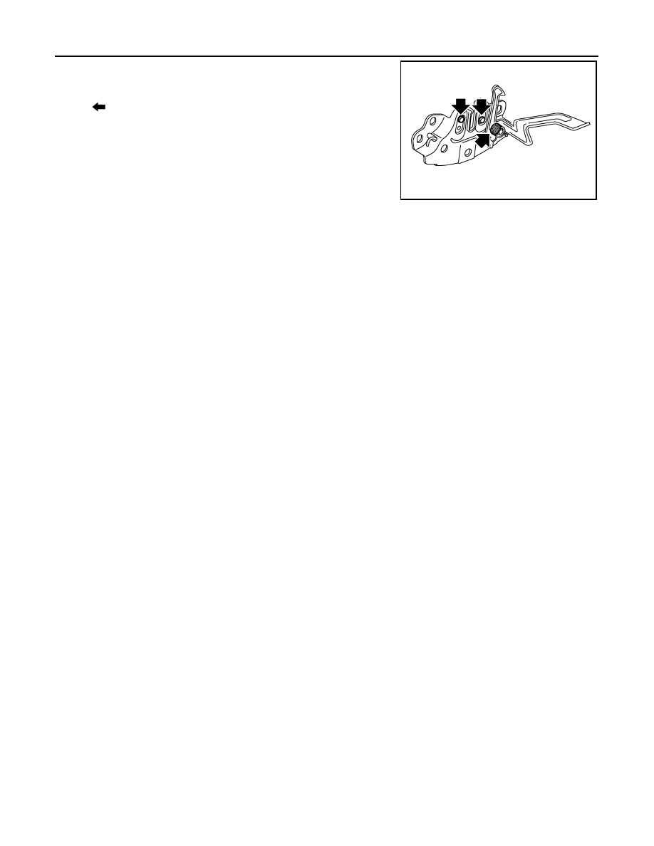
5.
Check the hood lock lubrication condition. If necessary, apply
body grease to hood lock.
: Grease up point
JMKIA5674ZZ
|
|
|
DLK-462 < REMOVAL AND INSTALLATION > HOOD LOCK 5. Check the hood lock lubrication condition. If necessary, apply : Grease up point JMKIA5674ZZ |