Nissan Quest E52. Manual - part 43


  Index      Nissan     Nissan Quest E52 (2011-2014 year) - Service and Repair Manual


Search            


Content   ..  41  42  43  44   ..


Nissan Quest E52. Manual - part 43


AV

COMPONENT PARTS

AV-51

< SYSTEM DESCRIPTION >

[DISPLAY AUDIO]

C

D

E

F

G

H

I

J

K

L

M

B

A

O

P

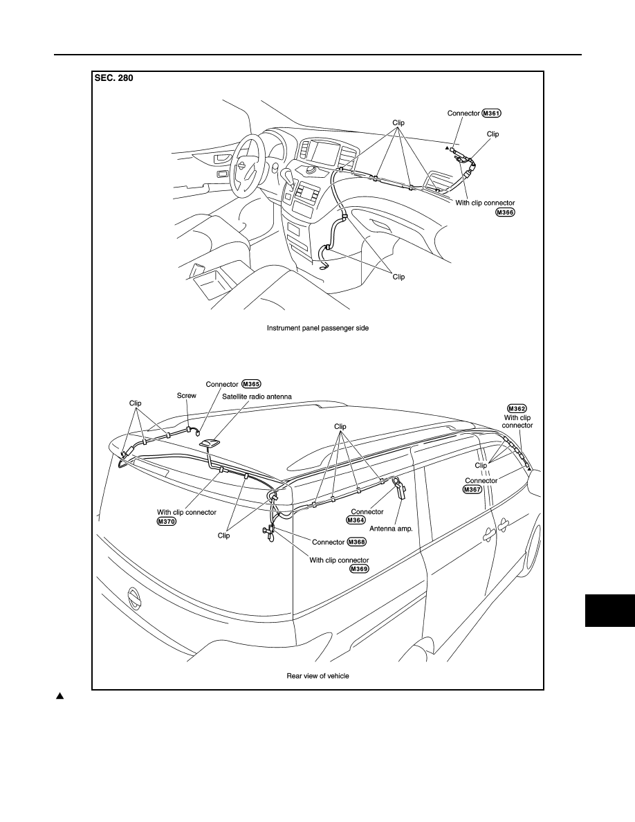
ANTENNA FEEDER LAYOUT

: Indicates that the part is connected at points with same symbol in actual vehicle.

JSNIA4724GB

AV-52

< SYSTEM DESCRIPTION >

[DISPLAY AUDIO]

COMPONENT PARTS

Rear View Camera 

INFOID:0000000009651930

• The rear view camera is installed to the back door finisher. 
• Super-small CCD camera (color) using CCD

*

 for the image pickup

element is adopted.

• With the mirror processing function, a mirror image is sent as if it is

viewed by a rear view mirror.

• Power for the camera is supplied from the audio unit, and the

image at the rear of the vehicle is sent to the audio unit. 

NOTE:
*: Abbreviation of Charge Coupled Device. CCD can turn incident
light from the lens into electrons and memorize the image like a
photo. 

Specification

JSNIA6373ZZ

Manufacturer name

Panasonic corporation

Image pickup element

1/4-inch interline CCD color

Effective number of pixels 

Approx. 250,000 pixels (510 

×

 492) 

Minimum brightness

2 lx

Angle of view

H: 137

°

 V: 92

°

Image

With mirror processing function 

AV

SYSTEM

AV-53

< SYSTEM DESCRIPTION >

[DISPLAY AUDIO]

C

D

E

F

G

H

I

J

K

L

M

B

A

O

P

SYSTEM

DISPLAY AUDIO SYSTEM

DISPLAY AUDIO SYSTEM : System Description

INFOID:0000000009651931

SYSTEM DIAGRAM

DESCRIPTION

Display audio system is equipped with the following functions (display unit is built in to audio unit).

Operating Signal

Display audio system operation can be performed with audio switch and steering switch.

COMMUNICATION SIGNAL

• Audio unit function by transmitting/receiving data one by one with TEL adapter unit (slave unit) that config-

ures them completely as a master unit by connecting between units that configure display audio system with
two AV communication lines (H, L).

• Two AV communication lines (H, L) adopt a twisted pair line that is resistant to noise.

AUDIO FUNCTION

• The audio unit has a 4.3-inch liquid crystal color display.
• The adoption of CD drive, USB connector, and auxiliary input jack (stereo mini jack) enables the playback of

various kinds of media.

• The MP3/WMA/AAC playback function enables music to play for a long time: the user need not change the

CD during a long trip. The text display function is also adopted so that the title name and artist name of the
ID3 tag/WMA/AAC tag can be displayed.
NOTE:
• MP3 stands for MPEG AUDIO LAYER3. It is the compression standard defined by “MPEG”, a joint activity

organization of ISO and IEC (the international standardization groups).

JSNIA5349GB

FUNCTION NAME

Audio function

Hands-free phone function

Rear view monitor function

AV-54

< SYSTEM DESCRIPTION >

[DISPLAY AUDIO]

SYSTEM

• WMA stands for Windows Media

®

 Audio. It is the sound data compression standard formulated by Micros

oft Corporation.

• AAC is abbreviation of Advanced Audio Coding. It is the sound data compression method standardized in

an animation compression standard (MPEG).

• The audio system is equipped with the following functions.

AM/FM Radio

• AM/FM radio tuner is built into audio unit.
• AM/FM radio wave is received by radio antenna, next it is amplified by antenna amp., and finally it is input to

audio unit. 

• FM radio wave is received by FM sub antenna, and it is transmitted to the audio unit directly.
• Audio unit outputs the sound signal to each speaker.

Satellite Radio

• Radio signal is received by satellite radio antenna and transmitted to audio unit.
• Audio unit outputs the sound signal to each speaker.

CD

• CD function is built into audio unit.
• Audio unit outputs sound signal to each speaker when CD is inserted to audio unit.
• For further information about CD function specifications, refer to 

AV-45, "Audio Unit"

.

Auxiliary input

• Auxiliary input jack (stereo mini jack) installed to the audio fascia. 
• Audio played back by external equipment (e.g. iPod

®

 and portable audio) is outputted from the vehicle

speakers via the auxiliary input jack installed to the audio fascia. 

• In auxiliary input mode, only sound volume and sound quality can be operated with the audio unit.

USB Connection

• iPod

®

 or music files in USB memory can be played. 

• iPod

®

 sound signals are transmitted from USB connector to each speaker via audio unit.

• iPod

®

 is recharged when connected to USB connector.

• Compliant USB memory and data recorded are limited. 

• Only files that meet the following conditions will be played.

iPod

®

 is a trademark of Apple inc., registered in the U.S. and other countries.

NOTE:
• The audio unit does not support the display of static images and videos.
• Use the enclosed USB harness when connecting iPod

®

 to USB connector.

Speed Sensitive Volume

FUNCTION

AM/FM radio

Satellite radio

CD

Auxiliary input

USB connection

Speed sensitive volume

USB memory

USB2.0

File system 

FAT16

FAT32

Music file

File format

“MP3”, “WMA”

File extension

“.mp3”, “.wma”

Maximum file size

800 MB


Content   ..  41  42  43  44   ..