Nissan Quest E52. Manual - part 42


  Index      Nissan     Nissan Quest E52 (2011-2014 year) - Service and Repair Manual


Search            


Content   ..  40  41  42  43   ..


Nissan Quest E52. Manual - part 42


AV

COMPONENT PARTS

AV-47

< SYSTEM DESCRIPTION >

[DISPLAY AUDIO]

C

D

E

F

G

H

I

J

K

L

M

B

A

O

P

• *1: If the reflectance of the surface of the media is low, the data may not be read.
• *2: It may not be used if it is not updated to the latest firmware or partial functions may not work if it is used. 
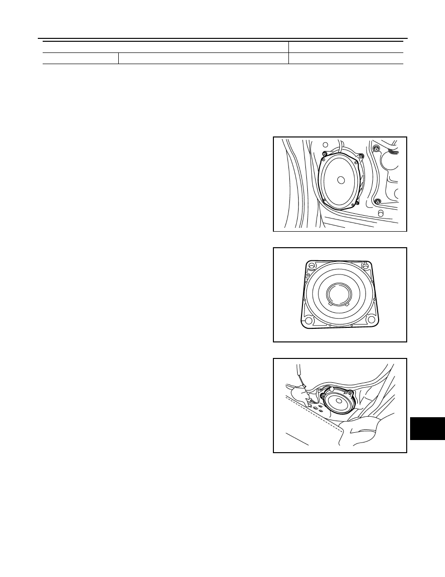
Speaker

INFOID:0000000009651922

6 speakers system is adopted.

FRONT DOOR WOOFER

φ

 15.0 

×

 23.0 cm (6 

×

 9 in) speaker is installed to the bottom of the front door.

• Sound signal is input from the audio unit to output low range

sounds. 

FRONT SQUAWKER

φ

 6.5 cm (2 in) squawker is installed to the side of instrument

panel.

• Sound signal is input from the audio unit to output high and mid

range sounds. 

SLIDE DOOR SPEAKER

φ

 16cm (6.5 in) speaker is located at the lower part of the back of

the slide door. 

• Sound signal is input from the audio unit to output high, mid, and

low range sounds. 

Auxiliary input

φ

 3.5 mm (0.1 in) stereo mini jack

Camera controller

Guideline display function

Width/distance display

Rated input

: 20 W

Maximum 
input

: 40 W

Impedance

: 2 

JSNIA3401ZZ

Rated input

: 7 W

Maximum 
input

: 40 W

Impedance

: 4 

JSNIA3402ZZ

Rated input

: 20 W

Maximum 
input

: 40 W

Impedance

: 2 

JSNIA3405ZZ

AV-48

< SYSTEM DESCRIPTION >

[DISPLAY AUDIO]

COMPONENT PARTS

TEL Adapter Unit

INFOID:0000000009651923

• Inputs the TEL voice signal from TEL antenna and outputs it to the

audio unit

• It is connected with the audio unit via AV communication and con-

trolled with the audio unit.

TEL Antenna

INFOID:0000000009651924

Receives the TEL voice signal from cellular phone and outputs it to
the TEL adapter unit.

Microphone

INFOID:0000000009651925

• The voice control/TEL microphone is installed on the left side of

the map lamp assembly. 

• The power is supplied from the TEL adapter unit to the micro-

phone, transmitting sound signals to the TEL adapter unit at the
voice control or during hands-free phone communication.

USB Connector

INFOID:0000000009651926

• USB connector is installed to the console box. 
• iPod

®

 and USB memory can be connected to the audio unit.

JSNIA4236ZZ

JSNIA4237ZZ

JPNIA1448ZZ

JPNIA1447ZZ

AV

COMPONENT PARTS

AV-49

< SYSTEM DESCRIPTION >

[DISPLAY AUDIO]

C

D

E

F

G

H

I

J

K

L

M

B

A

O

P

Steering Switch

INFOID:0000000009651927

• Operations for audio and hands-free phone, etc. are possible.
• This switch is connected to the TEL adapter unit, and the switch

operation signal is transmitted to the TEL adapter unit via voltage
multiplex communication.

Antenna amp., Radio Antenna, and Antenna Feeder

INFOID:0000000009651928

RADIO ANTENNA

• AM/FM radio main antenna is located on the right rear side window glass and FM radio sub antenna on the

left rear side window glass.

• The AM/FM radio main antenna path has an antenna amp. to obtain sufficient reception power.

CAUTION:

Affixing any mirror-type window films or metallic items (e.g. commercial antenna) on the rear side win-
dow glass causes a reduction in the radio receiver sensitivity.

JSNIA4329ZZ

JSNIA4326GB

AV-50

< SYSTEM DESCRIPTION >

[DISPLAY AUDIO]

COMPONENT PARTS

ANTENNA FEEDER LAYOUT

: Indicates that the part is connected at points with same symbol in actual vehicle.

Satellite Radio Antenna

INFOID:0000000009651929

SATELLITE RADIO ANTENNA

• Satellite radio antenna is installed to the rear center of the roof.
• Receives satellite radio waves and outputs it to audio unit.

JSNIA4724GB


Content   ..  40  41  42  43   ..