Nissan Cube. Manual - part 995
TM-236
< UNIT REMOVAL AND INSTALLATION >
[CVT: RE0F08B]
TRANSAXLE ASSEMBLY
• Transmission range switch connector
• Primary speed sensor connector
• Secondary speed sensor connector
• Ground
6.
Remove control cable and bracket from transaxle assembly. Refer to
.
7.
Remove CVT water hoses. Refer to
TM-230, "WATER HOSE : Exploded View"
8.
Remove CVT water tubes. Refer to
TM-230, "WATER HOSE : Exploded View"
.
9.
Remove CVT fluid level gauge.
10. Remove CVT fluid charging pipe.
11. Remove O-ring from CVT fluid charging pipe.
12. Remove starter motor. Refer to
.
13. Remove engine under cover.
14. Turn crankshaft, and remove the four tightening nuts for drive plate and torque converter.
CAUTION:
When turning crankshaft, turn it clockwise as viewed from the front of the engine.
15. Remove front drive shafts. Refer to
.
16. Remove heat insulator. Refer to
17. Support transaxle assembly with a transmission jack.
CAUTION:
When setting the transmission jack, be careful not to collide against drain plug.
18. Remove engine mounting insulator (LH). Refer to
.
19. Remove engine mounting bracket support (LH). Refer to
.
20. Remove rear engine mounting bracket. Refer to
21. Remove rear torque rod. Refer to
.
22. Support engine assembly with a transmission jack.
CAUTION:
When setting the transmission jack, be careful not to collide against drain plug.
23. Remove engine mounting bracket (LH). Refer to
.
24. Remove bolts fixing transaxle assembly to engine assembly.
25. Remove transaxle assembly from vehicle.
CAUTION:
• Secure torque converter to prevent it from dropping.
• Secure transaxle assembly to a transmission jack.
26. Remove CVT fluid cooler tubes. Refer to
TM-231, "CVT FLUID COOLER HOSE : Exploded View"
INSTALLATION
Note the following, and install in the reverse order of removal.
CAUTION:
• Never reuse O-ring.
• Apply grease to O-ring.
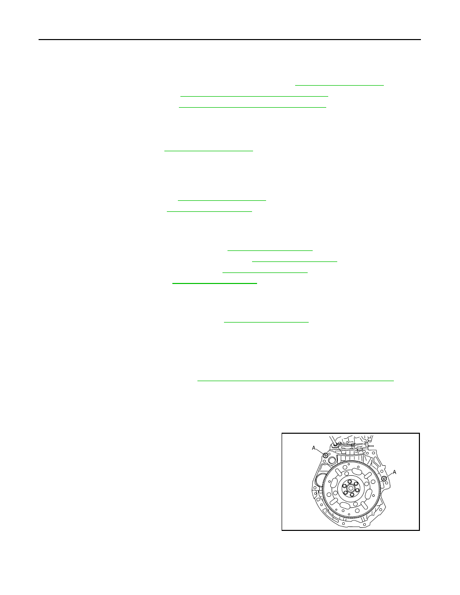
• Check fitting of dowel pins (A) when installing transaxle assembly
to engine assembly.
SCIA6618J