Nissan Cube. Manual - part 996


  Index      Nissan     Nissan Cube (2014 year) - Service and Repair Manual


Search            


Content   ..  994  995  996  997   ..


Nissan Cube. Manual - part 996


TM-240

< SERVICE DATA AND SPECIFICATIONS (SDS) 

[CVT: RE0F08B]

SERVICE DATA AND SPECIFICATIONS (SDS)

SERVICE DATA AND SPECIFICATIONS (SDS)

SERVICE DATA AND SPECIFICATIONS (SDS)

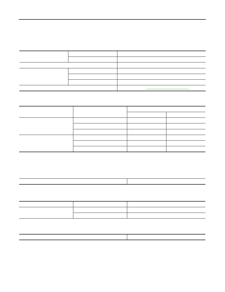
General Specification

INFOID:0000000009949121

Vehicle Speed When Shifting Gears

INFOID:0000000009949122

Unit: rpm

CAUTION:

Lock-up clutch is engaged when vehicle speed is approximately 18 km/h (11 MPH) to 90 km/h (56 MPH).

Stall Speed

INFOID:0000000009949123

Unit: rpm

Line Pressure

INFOID:0000000009949124

Unit: kPa (kg/cm

2

, psi)

Torque Converter

INFOID:0000000009949125

Applied model

Engine

MR18DE

Axle

2WD

Transaxle model

RE0F08B

Transmission gear ratio

D range

2.561 – 0.427

Reverse

2.689

Final drive

5.473

Recommended fluid and fluid capacity

Refer to 

MA-10, "Fluids and Lubricants"

.

 Throttle position

Shift pattern

Engine speed

At 40 km/h (25 MPH)

At 60 km/h (37 MPH)

2/8

“D” position

1,300 – 3,100

1,400 – 3,500

Overdrive OFF condition

2,200 – 3,000

2,800 – 3,600

“L” position

3,100 – 4,000

3,800 – 4,700

8/8

“D” position

3,600 – 4,500

4,400 – 5,300

Overdrive OFF condition

3,600 – 4,500

4,400 – 5,300

“L” position

3,600 – 4,500

4,400 – 5,300

Stall speed

2,600 – 3,150

Select position

Engine speed

Line pressure

“R”, “D”

Idle speed

650 (6.63, 94.3)

Stall speed

4,250 (43.35, 616.3)

Dimension “A” between end of converter housing and torque converter

14.4 mm (0.57 in)

VTL-1

VENTILATION, HEATER & AIR CONDITIONER

C

D

E

F

G

H

J

K

L

M

SECTION 

VTL

A

B

VTL

N

O

P

CONTENTS

VENTILATION SYSTEM

SYSTEM DESCRIPTION  ..............................

2

VENTILATION SYSTEM  .....................................

2

System Description  ...................................................

2

PRECAUTION ...............................................

3

PRECAUTIONS ...................................................

3

Precaution for Supplemental Restraint System 
(SRS) "AIR BAG" and "SEAT BELT PRE-TEN-
SIONER" .................................................................
..

3

Precautions for Removing of Battery Terminal  .........

3

Precaution for Procedure without Cowl Top Cover 

......

4

PREPARATION ............................................

5

PREPARATION ...................................................

5

Commercial Service Tool  ..........................................

5

PERIODIC MAINTENANCE ..........................

6

IN-CABIN MICROFILTER  ...................................

6

Exploded View  ..........................................................

6

Removal and Installation ...........................................

6

Replacement .............................................................

6

REMOVAL AND INSTALLATION ................

7

DUCT AND GRILLE ............................................

7

Exploded View  ..........................................................

7

CENTER VENTILATOR GRILLE  ................................

8

CENTER VENTILATOR GRILLE : Removal and 
Installation ...............................................................
..

8

SIDE VENTILATOR GRILLE  ......................................

8

SIDE VENTILATOR GRILLE : Removal and In-
stallation ..................................................................
.

8

CENTER VENTILATOR DUCT  ...................................

9

CENTER VENTILATOR DUCT : Removal and In-
stallation ..................................................................
.

9

SIDE VENTILATOR DUCT  .........................................

9

SIDE VENTILATOR DUCT : Removal and Instal-
lation ........................................................................
.

9

FRONT DEFROSTER NOZZLE ..................................

9

FRONT DEFROSTER NOZZLE : Removal and In-
stallation ..................................................................
.

9

SIDE DEFROSTER NOZZLE .....................................

10

SIDE DEFROSTER NOZZLE : Removal and In-
stallation ..................................................................

10

REAR FOOT DUCT 1  ................................................

10

REAR FOOT DUCT 1 : Removal and Installation ....

10

REAR FOOT DUCT 2  ................................................

10

REAR FOOT DUCT 2 : Removal and Installation ....

11

FOOT DUCT ...............................................................

11

FOOT DUCT : Removal and Installation  .................

11

BLOWER MOTOR  ............................................

13

Exploded View .........................................................

13

Removal and Installation  .........................................

13

VTL-2

< SYSTEM DESCRIPTION >

VENTILATION SYSTEM

SYSTEM DESCRIPTION

VENTILATION SYSTEM

System Description

INFOID:0000000009946826

OUTLINE

Ventilation system is controlled by A/C auto amp. (AUTOMATIC AIR CONDITIONING) or A/C control (MAN-
UAL AIR CONDITIONING). For details of air conditioning system, refer to 

HAC-15, "System Description"

(AUTOMATIC AIR CONDITIONING), 

HAC-141, "System Description"

 (MANUAL AIR CONDITIONING).

AIR FLOW

Front

Rear

×

: Applicable

JPIIA1716ZZ

JPIIA1717ZZ

MODE/DEF position in-

dication

AIR OUTLET

Ventilator (1)

Ventilator (2)

Foot (3)

Defroster (4)

×

×

×

×

×

×

×

×

×

×

×

×

×

PRECAUTIONS

VTL-3

< PRECAUTION >

C

D

E

F

G

H

J

K

L

M

A

B

VTL

N

O

P

PRECAUTION

PRECAUTIONS

Precaution for Supplemental Restraint System (SRS) "AIR BAG" and "SEAT BELT 
PRE-TENSIONER"

INFOID:0000000009946827

The Supplemental Restraint System such as “AIR BAG” and “SEAT BELT PRE-TENSIONER”, used along
with a front seat belt, helps to reduce the risk or severity of injury to the driver and front passenger for certain
types of collision. This system includes seat belt switch inputs and dual stage front air bag modules. The SRS
system uses the seat belt switches to determine the front air bag deployment, and may only deploy one front
air bag, depending on the severity of a collision and whether the front occupants are belted or unbelted.
Information necessary to service the system safely is included in the “SRS AIR BAG” and “SEAT BELT” of this
Service Manual.

WARNING:

Always observe the following items for preventing accidental activation.
• To avoid rendering the SRS inoperative, which could increase the risk of personal injury or death in

the event of a collision that would result in air bag inflation, all maintenance must be performed by
an authorized NISSAN/INFINITI dealer.

• Improper maintenance, including incorrect removal and installation of the SRS, can lead to personal

injury caused by unintentional activation of the system. For removal of Spiral Cable and Air Bag
Module, see “SRS AIR BAG”.

• Never use electrical test equipment on any circuit related to the SRS unless instructed to in this Ser-

vice Manual. SRS wiring harnesses can be identified by yellow and/or orange harnesses or harness
connectors.

PRECAUTIONS WHEN USING POWER TOOLS (AIR OR ELECTRIC) AND HAMMERS

WARNING:

Always observe the following items for preventing accidental activation.
• When working near the Air Bag Diagnosis Sensor Unit or other Air Bag System sensors with the

ignition ON or engine running, never use air or electric power tools or strike near the sensor(s) with
a hammer. Heavy vibration could activate the sensor(s) and deploy the air bag(s), possibly causing
serious injury.

• When using air or electric power tools or hammers, always switch the ignition OFF, disconnect the

battery, and wait at least 3 minutes before performing any service.

Precautions for Removing of Battery Terminal

INFOID:0000000010138604

•  When removing the 12V battery terminal, turn OFF the ignition

switch and wait at least 30 seconds.
NOTE:
ECU may be active for several tens of seconds after the ignition
switch is turned OFF. If the battery terminal is removed before ECU
stops, then a DTC detection error or ECU data corruption may
occur.

•  For vehicles with the 2-batteries, be sure to connect the main bat-

tery and the sub battery before turning ON the ignition switch.
NOTE:
If the ignition switch is turned ON with any one of the terminals of
main battery and sub battery disconnected, then DTC may be
detected.

•  After installing the 12V battery, always check "Self Diagnosis Result" of all ECUs and erase DTC.

NOTE:
The removal of 12V battery may cause a DTC detection error.

SEF289H


Content   ..  994  995  996  997   ..