Nissan Cube. Manual - part 994


  Index      Nissan     Nissan Cube (2014 year) - Service and Repair Manual


Search            


Content   ..  992  993  994  995   ..


Nissan Cube. Manual - part 994


TM-232

< REMOVAL AND INSTALLATION >

[CVT: RE0F08B]

CVT OIL WARMER SYSTEM

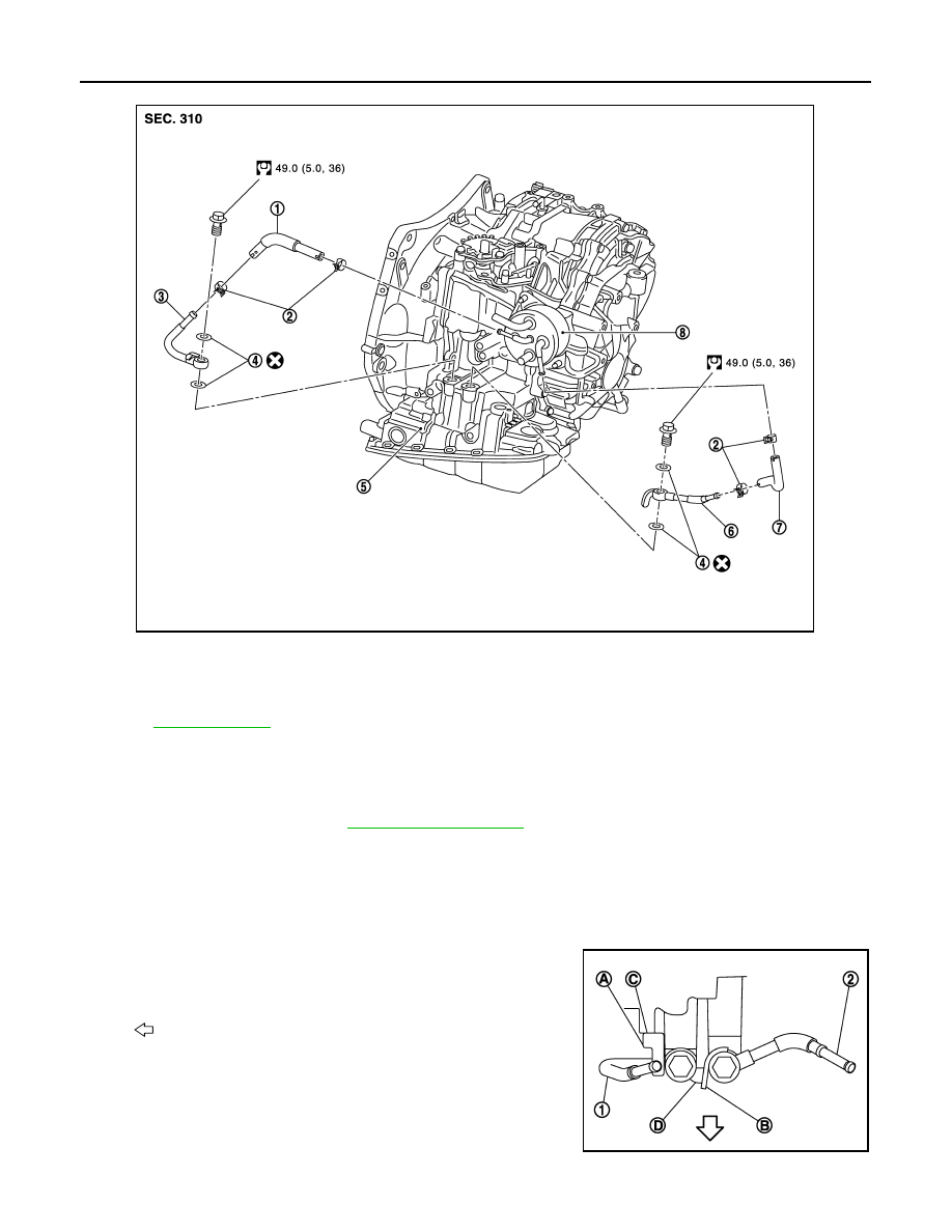
CVT FLUID COOLER HOSE : Removal and Installation

INFOID:0000000009949110

REMOVAL

1.

Remove air duct (inlet). Refer to 

EM-24, "Exploded View"

.

2.

Remove hose clamps, and remove CVT fluid cooler hose A.

3.

Remove hose clamps, and remove CVT fluid cooler hose B.

4.

Remove CVT fluid cooler tube A and CVT fluid cooler tube B.

INSTALLATION

Note the following, and install in the reverse order of removal.
• When installing CVT fluid cooler tube (1) and (2) to transaxle

assembly, install them so that CVT fluid cooler tube rotation stop-
per (A) and (B) touch to transaxle case (C) and (D).

1.

CVT fluid cooler hose A

2.

Hose clamp

3.

CVT fluid cooler tube A

4.

Gasket

5.

Transaxle assembly

6.

CVT fluid cooler tube B

7.

CVT fluid cooler hose B

8.

CVT oil warmer

Refer to 

GI-4, "Components"

 for symbols in the figure.

JSDIA1288GB

: Vehicle front

JPDIA0698ZZ

CVT OIL WARMER SYSTEM

TM-233

< REMOVAL AND INSTALLATION >

[CVT: RE0F08B]

C

E

F

G

H

I

J

K

L

M

A

B

TM

N

O

P

• Insert CVT fluid cooler hose according to dimension “A” described

below.

• Set hose clamps (1) at the both ends of fluid cooler hose (2) with

dimension “A” from the hose edge.

• Hose clamp should not interfere with the bulge.

*: Refer to the illustrations for the specific position of each hose clamp tab.

• The illustrations indicate the view from the hose ends.

• When installing hose clamps the center line of each clamp tab

should be positioned as shown in the figure.

CVT FLUID COOLER HOSE : Inspection

INFOID:0000000009949111

INSPECTION AFTER INSTALLATION

Check for CVT fluid leakage and check CVT fluid level. Refer to 

TM-206, "Inspection"

.

CVT OIL WARMER

CVT fluid cooler hose (1)

Insert side tube (2)

Dimension “A”

CVT fluid cooler hose A

CVT fluid cooler tube

End reaches the 2-stage 
bulge (B)

CVT oil warmer

CVT fluid cooler hose B

CVT oil warmer

CVT fluid cooler tube

JSDIA1289ZZ

Dimension “A”

: 5 – 7 mm (0.20 – 0.28 in)

SCIA8123E

CVT fluid cooler hose

Hose end

Paint mark

Position of hose clamp*

CVT fluid cooler hose A

CVT fluid cooler tube side

Vehicle front

A

CVT oil warmer side

Vehicle front

A

CVT fluid cooler hose B

CVT oil warmer side

Vehicle front

A

CVT fluid cooler tube side

Vehicle front

A

B

: Vehicle front

JPDIA0675ZZ

TM-234

< REMOVAL AND INSTALLATION >

[CVT: RE0F08B]

CVT OIL WARMER SYSTEM

CVT OIL WARMER : Exploded View

INFOID:0000000009949112

CVT OIL WARMER : Removal and Installation

INFOID:0000000009949113

REMOVAL

WARNING:

Never remove the radiator cap when the engine is hot. Serious burns could occur from high pressure
coolant escaping from the radiator.

CAUTION:

Perform this step engine is cold.

1.

Remove CVT water hose from CVT oil warmer. Refer to  

TM-230, "WATER HOSE : Exploded View"

.

2.

Remove CVT fluid cooler hose from CVT oil warmer. Refer to  

TM-231, "CVT FLUID COOLER HOSE :

Exploded View"

.

3.

Remove CVT oil warmer.

4.

Remove bracket.

INSTALLATION

Install in the reverse order of removal.

CVT OIL WARMER : Inspection

INFOID:0000000009949114

INSPECTION AFTER INSTALLATION

• Check for CVT fluid leakage and check CVT fluid level. Refer to 

TM-206, "Inspection"

.

• Start and warm up the engine. Visually check that there is no leakage of engine coolant and CVT fluid.

1.

CVT oil warmer

2.

Bracket

3.

Transaxle assembly

Refer to 

GI-4, "Components"

 for symbols in the figure.

JPDIA0725GB

TRANSAXLE ASSEMBLY

TM-235

< UNIT REMOVAL AND INSTALLATION >

[CVT: RE0F08B]

C

E

F

G

H

I

J

K

L

M

A

B

TM

N

O

P

UNIT REMOVAL AND INSTALLATION

TRANSAXLE ASSEMBLY

Exploded View

INFOID:0000000009949115

Removal and Installation

INFOID:0000000009949116

WARNING:

Never remove the radiator cap when the engine is hot. Serious burns could occur from high pressure
coolant escaping from the radiator.

CAUTION:

• Perform this step engine is cold.
• When replacing TCM and transaxle assembly as a set, replace transaxle assembly first and then

replace TCM. Refer to 

TM-68, "Description"

.

REMOVAL

1.

Remove battery. Refer to 

PG-82, "Exploded View"

.

2.

Remove air duct (inlet), air duct and air cleaner case. Refer to 

EM-24, "Exploded View"

.

3.

Remove air breather hose.

4.

Remove battery bracket.

5.

Disconnect following harness connector and wire harness.
• CVT unit connector. Refer to 

TM-202, "Removal and Installation Procedure for CVT Unit Connector"

.

1.

CVT fluid level gauge

2.

CVT fluid charging pipe

3.

O-ring

4.

Transaxle assembly

A.

: Tightening must be done following the installation procedure. Refer to 

TM-235, "Removal and Installation"

.

Refer to 

GI-4, "Components"

 for symbols in the figure.

JSDIA1185GB


Content   ..  992  993  994  995   ..