Nissan Cube. Manual - part 674


  Index      Nissan     Nissan Cube (2014 year) - Service and Repair Manual


Search            


Content   ..  672  673  674  675   ..


Nissan Cube. Manual - part 674


MWI-20

< SYSTEM DESCRIPTION >

METER SYSTEM

METER ILLUMINATION CONTROL

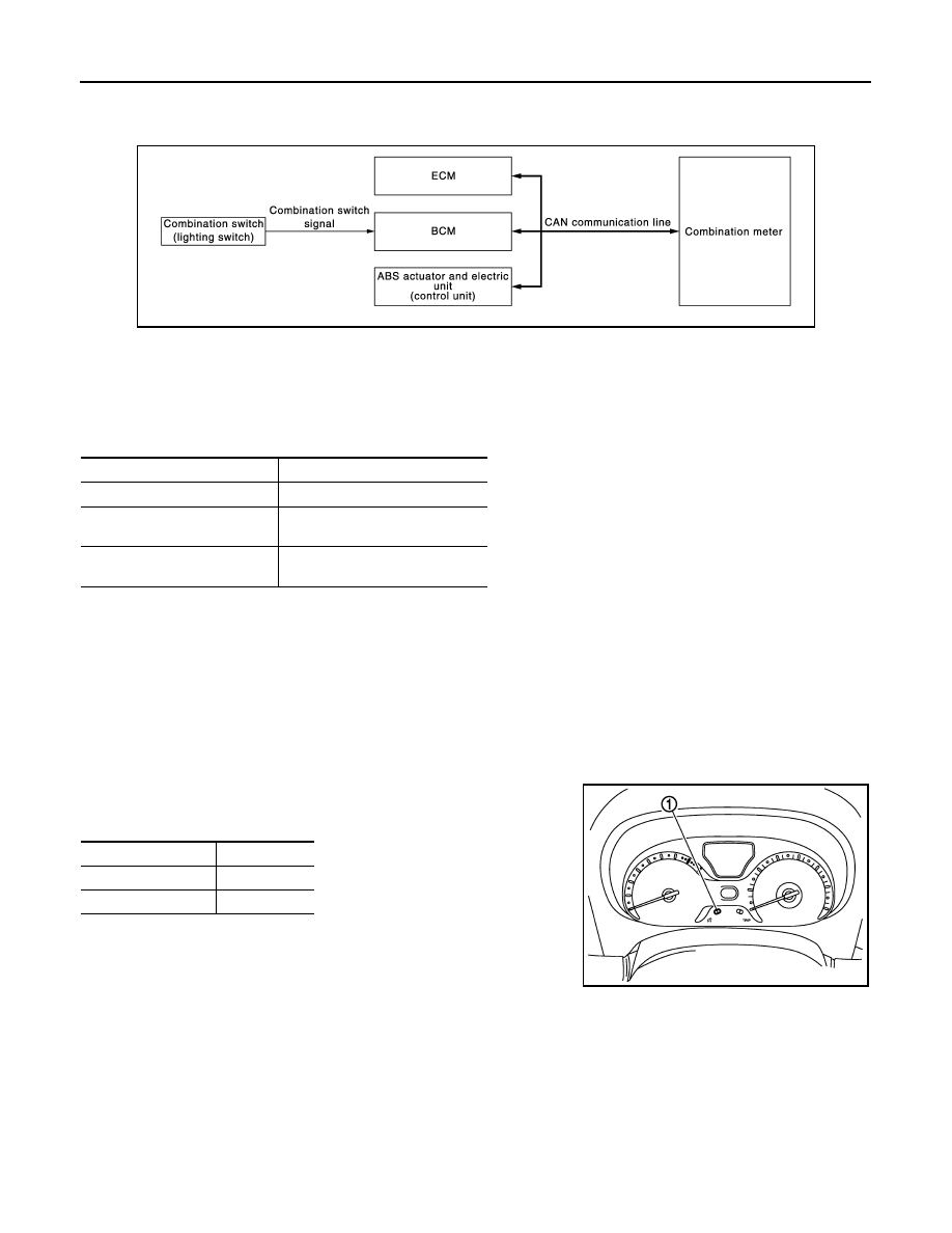
METER ILLUMINATION CONTROL : System Diagram

INFOID:0000000009945678

METER ILLUMINATION CONTROL : System Description

INFOID:0000000009945679

METER ILLUMINATION ON/OFF CONTROL FUNCTION

The combination meter receives the following signals to control meter illumination.

Turns ON Condition

Ignition switch ON

Turns OFF Condition

If any of the following conditions is fulfilled.
• During a crank with vehicle speed less than 1 km/h (0.6 MPH)
• Ignition switch OFF or ACC

METER ILLUMINATION CONTROL FUNCTION

• Combination meter is transferred to nighttime mode with position light request signal from BCM via CAN

communication.

• Meter illumination level can be adjusted in following steps using

the illumination control switch (1).

JPNIA1648GB

Signal name

Signal source

Ignition signal

Engine status signal
(CAN communication)

ECM

Vehicle speed signal
(CAN communication)

ABS actuator and control unit 

(control unit)

Condition

Steps

Daytime mode

22

Nighttime mode

22

JPNIA1665ZZ

MWI

METER SYSTEM

MWI-21

< SYSTEM DESCRIPTION >

C

D

E

F

G

H

I

J

K

L

M

B

A

O

P

METER ILLUMINATION CONTROL : Component Parts Location

INFOID:0000000010235629

METER ILLUMINATION CONTROL : Component Description

INFOID:0000000009945681

JSNIA6649ZZ

1.

Fuel level sensor unit

2.

ABS actuator and electric unit (con-
trol unit)
Refer to 

BRC-12, "Component Parts 

Location"

.

3.

Ambient sensor
Refer to 

HAC-24, "Component Parts 

Location"

.

4.

Oil pressure switch
Refer to 

EM-86, "Exploded View"

.

5.

A/C auto amp. (auto A/C models)
Refer to 

HAC-24, "Component Parts 

Location"

.

6.

IPDM E/R
• Refer  to 

PCS-5, "Component Parts 

Location"

 (with I-KEY).

• Refer  to 

PCS-36, "Component 

Parts Location"

 (without I-KEY).

7.

ECM
Refer to 

EC-36, 

"Component Parts Location"

.

8.

TCM
Refer to 

TM-71, "Component Parts 

Location"

.

9.

BCM
Refer to 

BCS-10, "Component Parts 

Location"

 (With intelligent key sys-

tem) or 

BCS-95, "Component Parts 

Location"

 (Without intelligent key sys-

tem).

10. Combination meter

A.

Under of right side rear seat 

Unit

Description

Combination meter

Controls the meter illumination with the meter control switch signal from the meter control switch 
and the position light request signal from BCM via CAN communication.

ECM

Transmits the engine status signal to the combination meter via CAN communication.

ABS actuator and electric unit 
(control unit)

Transmits the vehicle speed signal to the combination meter via CAN communication.

MWI-22

< SYSTEM DESCRIPTION >

METER SYSTEM

METER EFFECT FUNCTION

METER EFFECT FUNCTION : System Diagram

INFOID:0000000009945682

METER EFFECT FUNCTION : System Description

INFOID:0000000009945683

ENGINE-START EFFECT FUNCTION

For CVT Models

When "engine start" is read, the effect of comfort starts only once by turning on combination meter illumination
stepwise and sweeping the needles of speedometer and tachometer.

For M/T Models

When "engine start" is read, the effect of comfort starts only once by turning on combination meter illumination
and start-up lamp stepwise and sweeping the needles of speedometer and tachometer.

Outline of Control System  

System control is provided when all of the following conditions are met.

*: For CVT models

NOTE:

The engine-start effect function ends if any one of the above conditions is lost during the activation of this function.

BCM

Transmits the position light request signal to the combination meter via CAN communication.

Combination switch (lighting 
switch)

Using the combination switch reading function, BCM reads the combination switch status.

Unit

Description

JPNIA1649GB

Operating condition

Signal name

Signal source

Ignition switch

ON

Ignition signal

Shift position

*

P-range

Shift position signal
(CAN communication)

TCM

Engine status

More than 500 rpm

Engine speed signal
(CAN communication)

ECM

Except when cranking

Engine status signal
(CAN communication)

Vehicle speed

Less than 1 km/h (0.6 MPH)

Vehicle speed signal
(CAN communication)

ABS actuator and electric unit 

(control unit)

MWI

METER SYSTEM

MWI-23

< SYSTEM DESCRIPTION >

C

D

E

F

G

H

I

J

K

L

M

B

A

O

P

METER EFFECT FUNCTION : Component Parts Location

INFOID:0000000010235632

METER EFFECT FUNCTION : Component Description

INFOID:0000000009945685

JSNIA6649ZZ

1.

Fuel level sensor unit

2.

ABS actuator and electric unit (con-
trol unit)
Refer to 

BRC-12, "Component Parts 

Location"

.

3.

Ambient sensor
Refer to 

HAC-24, "Component Parts 

Location"

.

4.

Oil pressure switch
Refer to 

EM-86, "Exploded View"

.

5.

A/C auto amp. (auto A/C models)
Refer to 

HAC-24, "Component Parts 

Location"

.

6.

IPDM E/R
• Refer  to 

PCS-5, "Component Parts 

Location"

 (with I-KEY).

• Refer  to 

PCS-36, "Component 

Parts Location"

 (without I-KEY).

7.

ECM
Refer to 

EC-36, 

"Component Parts Location"

.

8.

TCM
Refer to 

TM-71, "Component Parts 

Location"

.

9.

BCM
Refer to 

BCS-10, "Component Parts 

Location"

 (With intelligent key sys-

tem) or 

BCS-95, "Component Parts 

Location"

 (Without intelligent key sys-

tem).

10. Combination meter

A.

Under of right side rear seat 

Unit

Description

Combination meter

Receives signals from each unit with the CAN communication and performs meter effect.

ECM

Transmits engine speed signal and engine status signal to the combination meter via CAN com-
munication.

TCM

Transmits shift position signal to the combination meter via CAN communication.

ABS actuator and electric unit 
(control unit)

Transmits vehicle speed signal to the combination meter via CAN communication.


Content   ..  672  673  674  675   ..