Nissan Cube. Manual - part 673


  Index      Nissan     Nissan Cube (2014 year) - Service and Repair Manual


Search            


Content   ..  671  672  673  674   ..


Nissan Cube. Manual - part 673


MWI-16

< SYSTEM DESCRIPTION >

METER SYSTEM

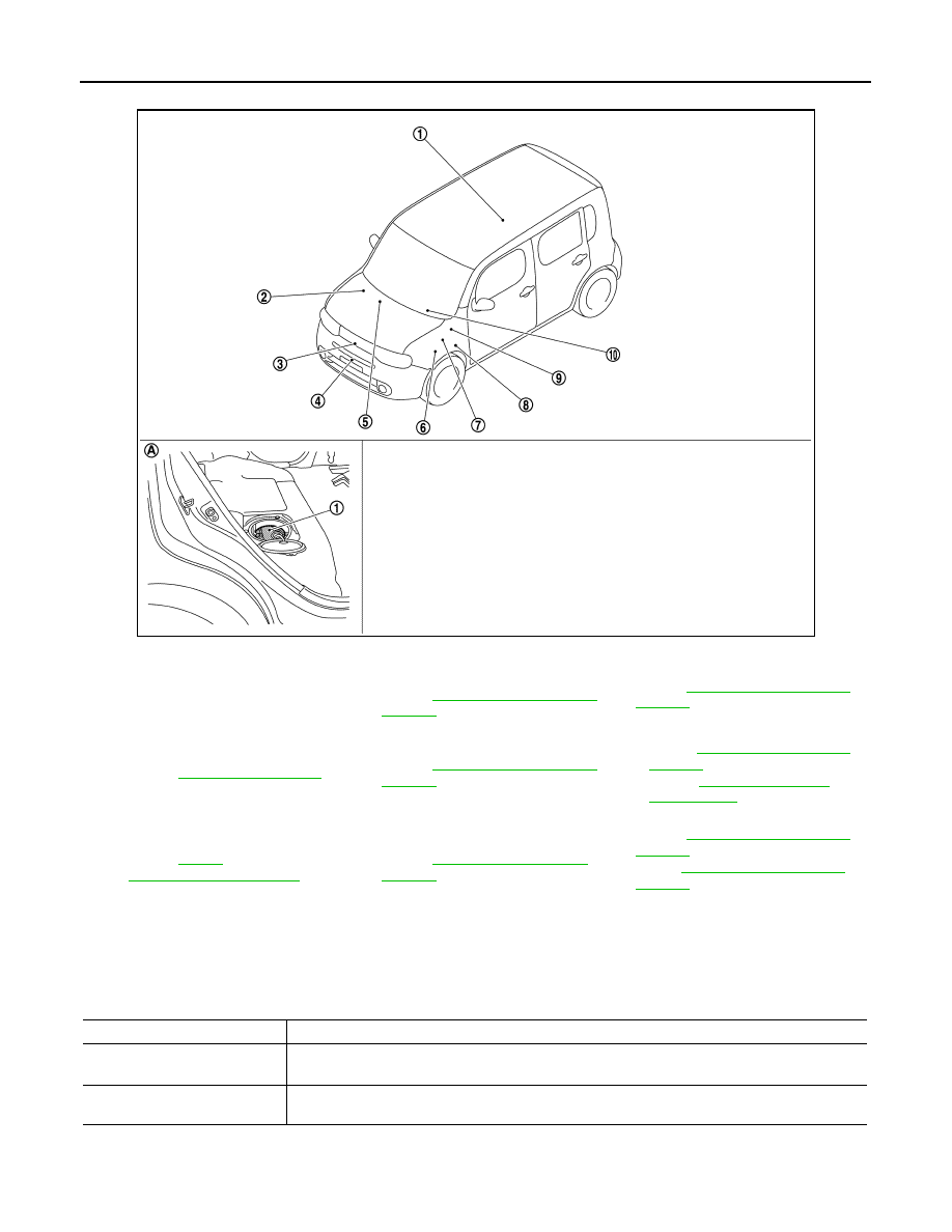
ODO/TRIP METER : Component Parts Location

INFOID:0000000010235310

ODO/TRIP METER : Component Description

INFOID:0000000009945669

SHIFT POSITION INDICATOR

JSNIA6649ZZ

1.

Fuel level sensor unit

2.

ABS actuator and electric unit (con-
trol unit)
Refer to 

BRC-12, "Component Parts 

Location"

.

3.

Ambient sensor
Refer to 

HAC-24, "Component Parts 

Location"

.

4.

Oil pressure switch
Refer to 

EM-86, "Exploded View"

.

5.

A/C auto amp. (auto A/C models)
Refer to 

HAC-24, "Component Parts 

Location"

.

6.

IPDM E/R
• Refer  to 

PCS-5, "Component Parts 

Location"

 (with I-KEY).

• Refer to 

PCS-36, "Component 

Parts Location"

 (without I-KEY).

7.

ECM
Refer to 

EC-36, 

"Component Parts Location"

.

8.

TCM
Refer to 

TM-71, "Component Parts 

Location"

.

9.

BCM
Refer to 

BCS-10, "Component Parts 

Location"

 (With intelligent key sys-

tem) or 

BCS-95, "Component Parts 

Location"

 (Without intelligent key sys-

tem).

10. Combination meter

A.

Under of right side rear seat 

Unit

Description

Combination meter

Converts the vehicle speed signal received from the ABS actuator and electric unit (control unit) via 
CAN communication to mileage, and it displays the accumulated mileage to the odo/trip meter. 

ABS actuator and electric unit
(control unit)

Transmits the vehicle speed signal to the combination meter via CAN communication. 

MWI

METER SYSTEM

MWI-17

< SYSTEM DESCRIPTION >

C

D

E

F

G

H

I

J

K

L

M

B

A

O

P

SHIFT POSITION INDICATOR : System Diagram

INFOID:0000000009945670

SHIFT POSITION INDICATOR : System Description

INFOID:0000000010244187

The combination meter receives the shift position signal from TCM via CAN communication, and displays the
shift position to the shift position indicator.

SHIFT POSITION INDICATOR : Component Parts Location

INFOID:0000000010235312

JPNIA1146GB

JSNIA6649ZZ

1.

Fuel level sensor unit

2.

ABS actuator and electric unit (con-
trol unit)
Refer to 

BRC-12, "Component Parts 

Location"

.

3.

Ambient sensor
Refer to 

HAC-24, "Component Parts 

Location"

.

4.

Oil pressure switch
Refer to 

EM-86, "Exploded View"

.

5.

A/C auto amp. (auto A/C models)
Refer to 

HAC-24, "Component Parts 

Location"

.

6.

IPDM E/R
• Refer  to 

PCS-5, "Component Parts 

Location"

 (with I-KEY).

• Refer  to 

PCS-36, "Component 

Parts Location"

 (without I-KEY).

MWI-18

< SYSTEM DESCRIPTION >

METER SYSTEM

SHIFT POSITION INDICATOR : Component Description

INFOID:0000000009945673

WARNING LAMPS/INDICATOR LAMPS

WARNING LAMPS/INDICATOR LAMPS : System Diagram

INFOID:0000000009945674

WARNING LAMPS/INDICATOR LAMPS : System Description

INFOID:0000000009945675

OIL PRESSURE WARNING LAMP

• IPDM E/R reads the ON/OFF signals from the oil pressure switch and transmits the oil pressure switch sig-

nal to the combination meter via BCM with the CAN communication. 

• The combination meter turns the oil pressure warning lamp ON (at the time of a reduction in hydraulic pres-

sure)/OFF (except at the time of a reduction in hydraulic pressure) according to the oil pressure switch signal
received via CAN communication. 

7.

ECM
Refer to 

EC-36, 

"Component Parts Location"

.

8.

TCM
Refer to 

TM-71, "Component Parts 

Location"

.

9.

BCM
Refer to 

BCS-10, "Component Parts 

Location"

 (With intelligent key sys-

tem) or 

BCS-95, "Component Parts 

Location"

 (Without intelligent key sys-

tem).

10. Combination meter

A.

Under of right side rear seat 

Unit

Description

Combination meter

Displays the shift position on the shift position indicator with shift position signal received from TCM 
via CAN communication.

TCM

Transmits shift position signal to the combination meter via CAN communication.

JSNIA6744GB

MWI

METER SYSTEM

MWI-19

< SYSTEM DESCRIPTION >

C

D

E

F

G

H

I

J

K

L

M

B

A

O

P

WARNING LAMPS/INDICATOR LAMPS : Component Parts Location

INFOID:0000000010235627

WARNING LAMPS/INDICATOR LAMPS : Component Description

INFOID:0000000009945677

JSNIA6649ZZ

1.

Fuel level sensor unit

2.

ABS actuator and electric unit (con-
trol unit)
Refer to 

BRC-12, "Component Parts 

Location"

.

3.

Ambient sensor
Refer to 

HAC-24, "Component Parts 

Location"

.

4.

Oil pressure switch
Refer to 

EM-86, "Exploded View"

.

5.

A/C auto amp. (auto A/C models)
Refer to 

HAC-24, "Component Parts 

Location"

.

6.

IPDM E/R
• Refer  to 

PCS-5, "Component Parts 

Location"

 (with I-KEY).

• Refer  to 

PCS-36, "Component 

Parts Location"

 (without I-KEY).

7.

ECM
Refer to 

EC-36, 

"Component Parts Location"

.

8.

TCM
Refer to 

TM-71, "Component Parts 

Location"

.

9.

BCM
Refer to 

BCS-10, "Component Parts 

Location"

 (With intelligent key sys-

tem) or 

BCS-95, "Component Parts 

Location"

 (Without intelligent key sys-

tem).

10. Combination meter

A.

Under of right side rear seat 

Unit

Description

Combination meter

Turns the oil pressure warning lamp ON/OFF according to the oil pressure switch signal received 
from BCM via CAN communication. 

IPDM E/R

Reads the ON/OFF signals from the oil pressure switch and transmits the oil pressure switch signal 
to the combination meter via BCM and CAN communication. 

Oil pressure switch

Refer to 

MWI-45, "Description"

BCM

Transmits the oil pressure switch signal received from IPDM E/R via CAN communication to the 
combination meter via CAN communication. 


Content   ..  671  672  673  674   ..