Nissan Cube. Manual - part 672


  Index      Nissan     Nissan Cube (2014 year) - Service and Repair Manual


Search            


Content   ..  670  671  672  673   ..


Nissan Cube. Manual - part 672


MWI-12

< SYSTEM DESCRIPTION >

METER SYSTEM

TACHOMETER : Component Description

INFOID:0000000009945657

ENGINE COOLANT TEMPERATURE GAUGE

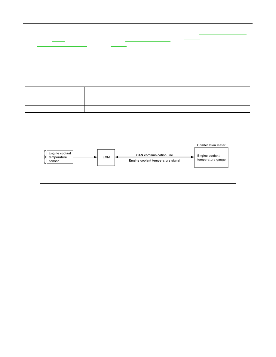
ENGINE COOLANT TEMPERATURE GAUGE : System Diagram

INFOID:0000000009945658

ENGINE COOLANT TEMPERATURE GAUGE : System Description

INFOID:0000000009945659

• ECM reads the engine coolant temperature signal from the engine coolant temperature sensor and transmits

the signal to the combination meter via CAN communication. 

• The combination meter indicates the engine coolant temperature to the engine coolant temperature gauge

according to the engine coolant temperature signal received via CAN communication. 

7.

ECM
Refer to 

EC-36, 

"Component Parts Location"

.

8.

TCM
Refer to 

TM-71, "Component Parts 

Location"

.

9.

BCM
Refer to 

BCS-10, "Component Parts 

Location"

 (With intelligent key sys-

tem) or 

BCS-95, "Component Parts 

Location"

 (Without intelligent key sys-

tem).

10. Combination meter

A.

Under of right side rear seat 

Unit

Description

Combination meter

Indicates the engine speed to the tachometer according to the engine speed signal received from 
ECM via CAN communication. 

ECM

Transmits the engine speed signal to the combination meter via CAN communication.

JPNIA1359GB

MWI

METER SYSTEM

MWI-13

< SYSTEM DESCRIPTION >

C

D

E

F

G

H

I

J

K

L

M

B

A

O

P

ENGINE COOLANT TEMPERATURE GAUGE : Component Parts Location

INFOID:0000000010244997

ENGINE COOLANT TEMPERATURE GAUGE : Component Description

INFOID:0000000009945661

FUEL GAUGE

JSNIA6649ZZ

1.

Fuel level sensor unit

2.

ABS actuator and electric unit (con-
trol unit)
Refer to 

BRC-12, "Component Parts 

Location"

.

3.

Ambient sensor
Refer to 

HAC-24, "Component Parts 

Location"

.

4.

Oil pressure switch
Refer to 

EM-86, "Exploded View"

.

5.

A/C auto amp. (auto A/C models)
Refer to 

HAC-24, "Component Parts 

Location"

.

6.

IPDM E/R
• Refer  to 

PCS-5, "Component Parts 

Location"

 (with I-KEY).

• Refer  to 

PCS-36, "Component 

Parts Location"

 (without I-KEY).

7.

ECM
Refer to 

EC-36, 

"Component Parts Location"

.

8.

TCM
Refer to 

TM-71, "Component Parts 

Location"

.

9.

BCM
Refer to 

BCS-10, "Component Parts 

Location"

 (With intelligent key sys-

tem) or 

BCS-95, "Component Parts 

Location"

 (Without intelligent key sys-

tem).

10. Combination meter

A.

Under of right side rear seat 

Unit

Description

Combination meter

Indicates the engine coolant temperature to the engine coolant temperature gauge according to the 
engine coolant temperature signal received from ECM via CAN communication. 

ECM

Transmits the engine coolant temperature signal to the combination meter via CAN communication. 

MWI-14

< SYSTEM DESCRIPTION >

METER SYSTEM

FUEL GAUGE : System Diagram

INFOID:0000000009945662

FUEL GAUGE : System Description

INFOID:0000000009945663

CONTROL OUTLINE

The combination meter reads the fuel level sensor signal from the fuel level sensor unit and indicates the fuel
level to the fuel gauge. 

REFUEL CONTROL

The combination meter accelerates the fuel gauge segment if the all conditions listed below are met, or the
ignition switch is ON from OFF.
• Ignition switch is ON position.
• The vehicle is not moving.
• The fuel level change by 15   (4 US gal, 3-1/4 Imp gal) or more.

FUEL GAUGE : Component Parts Location

INFOID:0000000010235295

JPNIA1663GB

JSNIA6649ZZ

MWI

METER SYSTEM

MWI-15

< SYSTEM DESCRIPTION >

C

D

E

F

G

H

I

J

K

L

M

B

A

O

P

FUEL GAUGE : Component Description

INFOID:0000000009945665

ODO/TRIP METER

ODO/TRIP METER : System Diagram

INFOID:0000000009945666

ODO/TRIP METER : System Description

INFOID:0000000009945667

• The ABS actuator and electric unit (control unit) reads the rectangular wave signal provided by the wheel

sensor and transmits the vehicle speed signal to the combination meter via CAN communication. 

• The combination meter converts the vehicle speed signal received via CAN communication to mileage, and

it displays the accumulated mileage to the odo/trip meter. 

1.

Fuel level sensor unit

2.

ABS actuator and electric unit (con-
trol unit)
Refer to 

BRC-12, "Component Parts 

Location"

.

3.

Ambient sensor
Refer to 

HAC-24, "Component Parts 

Location"

.

4.

Oil pressure switch
Refer to 

EM-86, "Exploded View"

.

5.

A/C auto amp. (auto A/C models)
Refer to 

HAC-24, "Component Parts 

Location"

.

6.

IPDM E/R
• Refer  to 

PCS-5, "Component Parts 

Location"

 (with I-KEY).

• Refer  to 

PCS-36, "Component 

Parts Location"

 (without I-KEY).

7.

ECM
Refer to 

EC-36, 

"Component Parts Location"

.

8.

TCM
Refer to 

TM-71, "Component Parts 

Location"

.

9.

BCM
Refer to 

BCS-10, "Component Parts 

Location"

 (With intelligent key sys-

tem) or 

BCS-95, "Component Parts 

Location"

 (Without intelligent key sys-

tem).

10. Combination meter

A.

Under of right side rear seat 

Unit

Description

Combination meter

Indicates the fuel gauge according to the fuel level sensor signal received from the fuel level sensor 
unit. 

Fuel level sensor unit

Refer to 

MWI-42, "Description"

.

JSNIA0293GB


Content   ..  670  671  672  673   ..