Nissan Cube. Manual - part 670
MWI-4
< BASIC INSPECTION >
DIAGNOSIS AND REPAIR WORKFLOW
BASIC INSPECTION
DIAGNOSIS AND REPAIR WORKFLOW
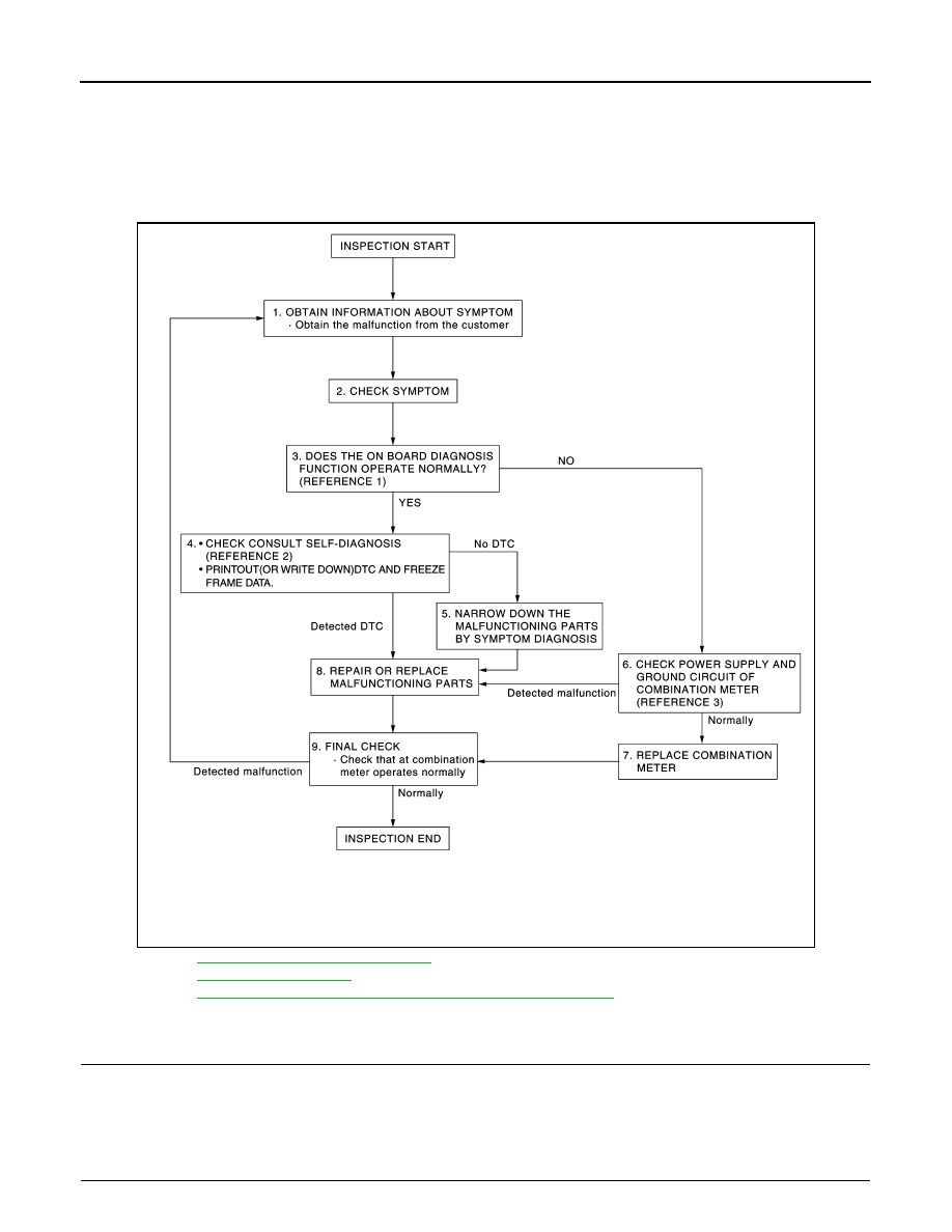
Work flow
INFOID:0000000009945645
OVERALL SEQUENCE
• Reference 1···
MWI-29, "Diagnosis Description"
.
• Reference 2···
.
• Reference 3···
MWI-39, "COMBINATION METER : Diagnosis Procedure"
.
DETAILED FLOW
1.
OBTAIN INFORMATION ABOUT SYMPTOM
Interview the customer to obtain as much information as possible about the conditions and environment under
which the malfunction occurred.
>> GO TO 2.
2.
CHECK SYMPTOM
JSNIA4484GB