Nissan Cube. Manual - part 664


  Index      Nissan     Nissan Cube (2014 year) - Service and Repair Manual


Search            


Content   ..  662  663  664  665   ..


Nissan Cube. Manual - part 664


MA-30

< SERVICE DATA AND SPECIFICATIONS (SDS) 

SERVICE DATA AND SPECIFICATIONS (SDS)

SERVICE DATA AND SPECIFICATIONS (SDS)

SERVICE DATA AND SPECIFICATIONS (SDS)

DRIVE BELT

DRIVE BELT : Drive Belt

INFOID:0000000009949453

DRIVE BELT

ENGINE COOLANT

ENGINE COOLANT : Periodical Maintenance Specification

INFOID:0000000009949454

ENGINE COOLANT CAPACITY (APPROXIMATE)

Unit: 

 (US qt, Imp qt)

ENGINE OIL

ENGINE OIL : Periodical Maintenance Specification

INFOID:0000000009949455

ENGINE OIL CAPACITY (APPROXIMATE)

Unit: 

 (US qt, lmp qt)

SPARK PLUG

SPARK PLUG : Spark Plug

INFOID:0000000009949456

SPARK PLUG

Unit: mm (in)

ROAD WHEEL

ROAD WHEEL : Road Wheel

INFOID:0000000010269337

ALUMINUM WHEEL 

STEEL WHEEL

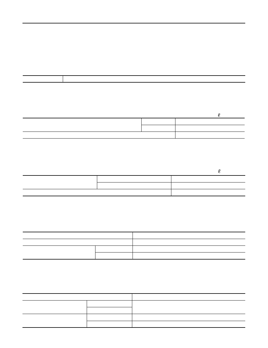
Tension of drive belt

Belt tension is not necessary, as it is automatically adjusted by drive belt auto-tensioner.

Engine coolant capacity (With reservoir tank at “MAX” level)

CVT models

7.1 (7-1/2, 6-1/4)

M/T models

6.8 (7-1/4, 6)

Reservoir tank engine coolant capacity (At “MAX” level)

0.7 (3/4, 5/8)

Drain and refill 

With oil filter change

4.1 (4-3/8, 3-5/8)

Without oil filter change

3.8 (4, 3-3/8)

Dry engine (Overhaul)

4.9 (5-1/8, 4-3/8)

Make

DENSO

Standard type

FXE20HR11

Gap (Nominal)

Standard

1.1 (0.043)

Limit

1.4 (0.055)

Item

Limit

Radial runout

Axial runout

Less than 0.3 mm (0.012 in)

Radial runout

Allowable unbalance

Dynamic (At flange)

Less than 10 g (0.35 oz) (one side)

Static (At flange)

Less than 20 g (0.70 oz)

SERVICE DATA AND SPECIFICATIONS (SDS)

MA-31

< SERVICE DATA AND SPECIFICATIONS (SDS) 

C

D

E

F

G

H

I

J

K

L

M

B

MA

N

O

A

Item

Limit

Radial runout

Conventional

Axial runout (Average)

Less than 0.8 mm (0.031 in)

Radial runout (Average)

Less than 0.5 mm (0.020 in)

Emergency

Axial runout (Average)

Less than 1.2 mm (0.031 in)

Radial runout (Average)

Less than 1.0 mm (0.020 in)

Allowable unbalance

Dynamic (At flange)

Less than 10 g (0.35 oz) (one side)

Static (At flange)

Less than 20 g (0.70 oz)

MIR-1

DRIVER CONTROLS

C

D

E

F

G

H

I

J

K

M

SECTION 

MIR

A

B

MIR

N

O

P

CONTENTS

MIRRORS

DTC/CIRCUIT DIAGNOSIS  ..........................

2

DOOR MIRROR ...................................................

2

Description ................................................................

2

Wiring Diagram - MIRROR SYSTEM - ......................

3

Component Inspection  ..............................................

4

SYMPTOM DIAGNOSIS  ...............................

6

SQUEAK AND RATTLE TROUBLE DIAG-
NOSES ................................................................

6

Work Flow  .................................................................

6

Inspection Procedure  ................................................

8

Diagnostic Worksheet  .............................................

10

PRECAUTION ..............................................

12

PRECAUTIONS ..................................................

12

Precaution for Supplemental Restraint System 
(SRS) "AIR BAG" and "SEAT BELT PRE-TEN-
SIONER" .................................................................

12

Precaution for Procedure without Cowl Top Cover 

....

12

Precautions for Removing of Battery Terminal  .......

13

PREPARATION ...........................................

14

PREPARATION ..................................................

14

Commercial Service Tools .....................................

14

REMOVAL AND INSTALLATION  ...............

15

INSIDE MIRROR  ...............................................

15

Exploded View .........................................................

15

Removal and Installation  .........................................

15

OUTSIDE MIRROR  ...........................................

16

DOOR MIRROR ASSEMBLY  ....................................

16

DOOR MIRROR ASSEMBLY : Exploded View  .......

16

DOOR MIRROR ASSEMBLY : Removal and In-
stallation ..................................................................

16

GLASS MIRROR ........................................................

16

GLASS MIRROR : Exploded View ..........................

17

GLASS MIRROR : Disassembly and Assembly  ......

17

DOOR MIRROR COVER  ...........................................

17

DOOR MIRROR COVER : Exploded View ..............

18

DOOR MIRROR COVER : Disassembly and As-
sembly .....................................................................

18

DOOR MIRROR REMOTE CONTROL 
SWITCH .............................................................

19

Exploded View .........................................................

19

Removal and Installation  .........................................

19

MIR-2

< DTC/CIRCUIT DIAGNOSIS >

DOOR MIRROR

DTC/CIRCUIT DIAGNOSIS

DOOR MIRROR

Description

INFOID:0000000009946000

Component

Function

Door mirror remote control 
switch

Mirror switch

It supplies power to mirror motor through mirror switch and changeover 
switch.

Changeover switch

It transmits the LH/RH control of door mirror that supplies power.

Door mirror

Door mirror motor

It makes mirror face operate from side to side and up and down via inte-
grated motor.


Content   ..  662  663  664  665   ..