Nissan Cube. Manual - part 662


  Index      Nissan     Nissan Cube (2014 year) - Service and Repair Manual


Search            


Content   ..  660  661  662  663   ..


Nissan Cube. Manual - part 662


MA-22

< PERIODIC MAINTENANCE >

CHASSIS MAINTENANCE

GEAR OIL : Inspection

INFOID:0000000009949436

OIL LEAKAGE

Make sure that gear oil is not leaking from transaxle or around it.
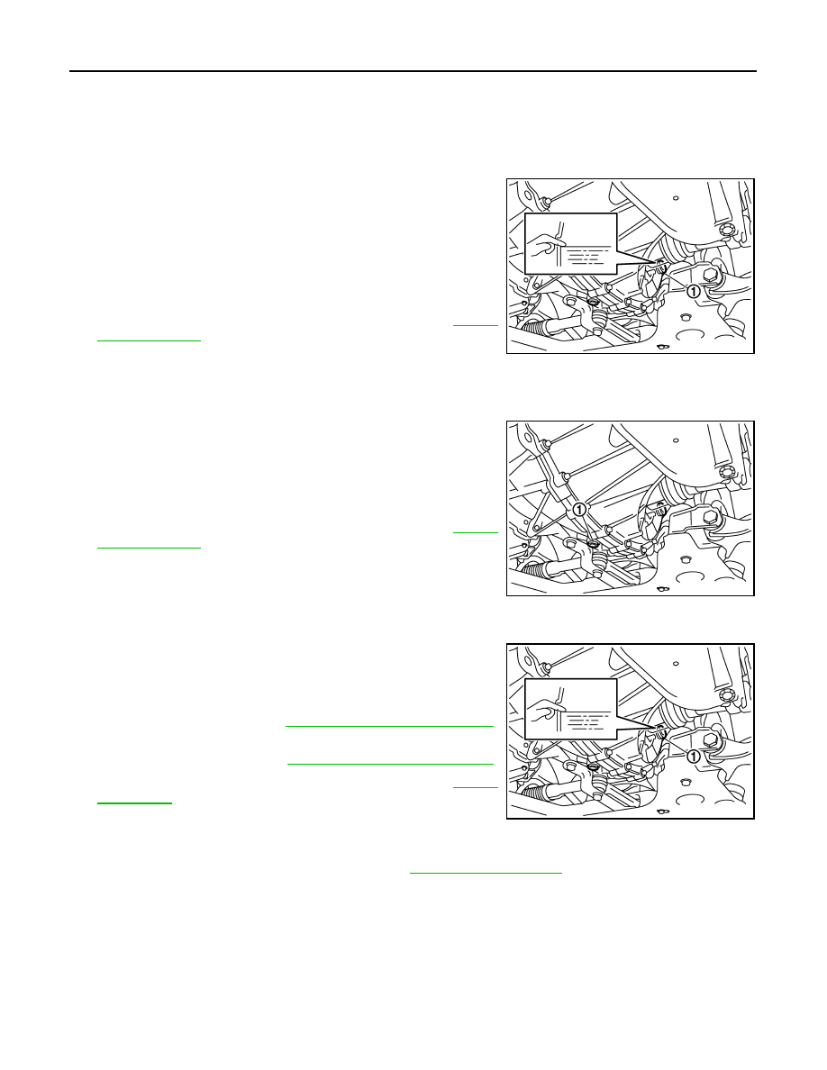
OIL LEVEL

1.

Remove filler plug (1) and gasket from transaxle case.

2.

Check the oil level from filler plug mounting hole as shown in the
figure.

CAUTION:

Never start engine while checking oil level.

3.

Set a gasket on filler plug and then install it to transaxle case.

CAUTION:

Never reuse gasket.

4.

Tighten filler plug to the specified torque. Refer to 

TM-27,

"Exploded View"

.

GEAR OIL : Draining

INFOID:0000000009949437

1.

Start engine and let it run to warm up transaxle.

2.

Stop engine. Remove drain plug (1) and gasket, using a socket
[Commercial service tool] and then drain gear oil.

3.

Set a gasket on drain plug and install it to clutch housing, using
a socket [Commercial service tool].

CAUTION:

Never reuse gasket.

4.

Tighten drain plug to the specified torque. Refer to 

TM-27,

"Exploded View"

.

GEAR OIL : Refilling

INFOID:0000000010269326

1.

Remove filler plug (1) and gasket from transaxle case. 

2.

Fill with new gear oil until oil level reaches the specified limit at
filler plug mounting hole as shown in the figure.

3.

After refilling gear oil, check the oil level. Refer to 

TM-17,

"Inspection"

.

4.

Set a gasket on filler plug and then install it to transaxle case.

CAUTION:

Never reuse gasket.

5.

Tighten filler plug to the specified torque. Refer to 

TM-27, "Exploded View"

.

CLUTCH FLUID

CLUTCH FLUID : Inspection

INFOID:0000000010269327

FLUID LEAKAGE

• Check clutch line for cracks, deterioration or other damage. Replace any damaged parts.
• Check for fluid leakage by fully depressing clutch pedal while engine is running.

CAUTION:

If leakage occurs around joints, reinstall the joints or, if necessary, replace damaged parts.

SCIA7623E

SCIA7622E

Oil grade and 
viscosity

: Refer to 

MA-10, "Fluids and Lubricants"

.

Oil capacity

: Refer to 

TM-63, "General Specification"

.

SCIA7623E

CHASSIS MAINTENANCE

MA-23

< PERIODIC MAINTENANCE >

C

D

E

F

G

H

I

J

K

L

M

B

MA

N

O

A

FLUID LEVEL

• Check that the fluid level in the reservoir tank is within the specified

range (MAX – MIN lines).

• Visually check for any fluid leakage around the reservoir tank.
• Check the clutch system for any leakage if the fluid level is

extremely low (lower than MIN).

WHEELS (BONDING WEIGHT TYPE)

WHEELS (BONDING WEIGHT TYPE) : Adjustment

INFOID:0000000010269334

BALANCING WHEELS (BONDING WEIGHT TYPE)

Preparation Before Adjustment

Using releasing agent, remove double-faced adhesive tape from the road wheel.

CAUTION:

• Be careful not to scratch the road wheel during removal.
• After removing double-faced adhesive tape, wipe clean traces of releasing agent from the road

wheel.

Wheel Balance Adjustment

• The details of the adjustment procedure are different for each model of wheel balancer. Therefore, refer to

each instruction manual.

• If a tire balance machine has adhesion balance weight mode settings and drive-in weight mode setting,

select and adjust a drive-in weight mode suitable for road wheels.

1.

Set road wheel on tire balance machine using the center hole as a guide. Start the tire balance machine.

2.

When inner and outer unbalance values are shown on the tire balance machine indicator, multiply outer
unbalance value by 5/3 to determine balance weight that should be used. Select the outer balance weight
with a value closest to the calculated value above and install to the designated outer position of, or at the
designated angle in relation to the road wheel.

CAUTION:

• Do not install the inner balance weight before installing the outer balance weight.
• Before installing the balance weight, be sure to clean the mating surface of the road wheel.

a.

Indicated unbalance value 

×

 5/3 = balance weight to be installed

Calculation example:
23 g (0.81 oz) 

×

 5/3 = 38.33 g (1.35 oz) 

 40 g (1.41 oz) bal-

ance weight (closer to calculated balance weight value)
NOTE:
Note that balance weight value must be closer to the calculated
balance weight value.
Example:
37.4 

 35 g (1.23 oz)

37.5 

 40 g (1.41 oz)

b.

Installed balance weight in the position.

JPFIA0007ZZ

SMA054D

MA-24

< PERIODIC MAINTENANCE >

CHASSIS MAINTENANCE

• When installing balance weight (1) to road wheels, set it into

the grooved area (A) on the inner wall of the road wheel as
shown in the figure so that the balance weight center (B) is
aligned with the tire balance machine indication position
(angle) (C).

CAUTION:

• Always use genuine NISSAN adhesion balance weights.
• Balance weights are non-reusable; always replace with

new ones.

• Do not install three or more sheets of balance weight.

c.

If calculated balance weight value exceeds 50 g (1.76 oz), install
two balance weight sheets in line with each other as shown in
the figure.

CAUTION:

Do not install one balance weight sheet on top of another.

3.

Start the tire balance machine again.

4.

Install drive-in balance weight on inner side of road wheel in the
tire balance machine indication position (angle).

CAUTION:

Do not install three or more balance weight.

5.

Start the tire balance machine. Check that inner and outer resid-
ual unbalance values is within the allowable unbalance value.

CAUTION:

If either residual unbalance value exceeds limit, repeat installation procedures.

TIRE ROTATION

• Follow the maintenance schedule for tire rotation service intervals.

Refer to 

MA-4, "Explanation of General Maintenance"

.

• When installing the wheel, tighten wheel nuts to the specified

torque. Refer to 

WT-46, "Exploded View"

.

CAUTION:

• Never include the T-type spare tire when rotating the tires.
• When installing wheels, tighten them diagonally by dividing

the work two to three times in order to prevent the wheels
from developing any distortion.

• Be careful not to tighten wheel nut at torque exceeding the

criteria for preventing strain of disc rotor.

• Use NISSAN genuine wheel nuts for aluminum wheels.

• Perform the ID registration, after tire rotation. Refer to 

WT-24, "Work Procedure"

.

BRAKE FLUID LEVEL AND LEAKS

JPEIC0040ZZ

Allowable unbalance value

Dynamic (At flange)

: Refer to 

WT-54, "Road Wheel"

.

Static (At flange)

: Refer to 

WT-54, "Road Wheel"

.

PEIA0033E

SMA829C

CHASSIS MAINTENANCE

MA-25

< PERIODIC MAINTENANCE >

C

D

E

F

G

H

I

J

K

L

M

B

MA

N

O

A

BRAKE FLUID LEVEL AND LEAKS : Inspection

INFOID:0000000009949441

• If fluid level is extremely low, check brake system for leaks.

BRAKE LINES AND CABLES

BRAKE LINES AND CABLES : Inspection

INFOID:0000000009949442

• Check brake fluid lines and parking brake cables for improper

attachment, leaks, chafing, abrasions, deterioration, etc.

BRAKE FLUID

BRAKE FLUID : Changing

INFOID:0000000009949443

1.

Drain brake fluid from each bleed valve.

2.

Refill until new brake fluid comes out from each bleed valve.
Use same procedure as in bleeding hydraulic system to refill
brake fluid.
Refer to 

BR-10, "Refilling"

 .

• Refill with recommended brake fluid.

Refer to 

MA-10, "Fluids and Lubricants"

.

• Never reuse drained brake fluid.
• Be careful not to splash brake fluid on painted areas.

DISC BRAKE

DISC BRAKE : Inspection

INFOID:0000000009949444

DISC ROTOR

Check condition, wear, and damage.

CALIPER

SFIA0066J

SBR389C

SBR419C


Content   ..  660  661  662  663   ..