Nissan Cube. Manual - part 601


  Index      Nissan     Nissan Cube (2014 year) - Service and Repair Manual


Search            


Content   ..  599  600  601  602   ..


Nissan Cube. Manual - part 601


INL-24

< DTC/CIRCUIT DIAGNOSIS >

INTERIOR ROOM LAMP POWER SUPPLY CIRCUIT

INTERIOR ROOM LAMP POWER SUPPLY CIRCUIT

Description

INFOID:0000000009950932

Provides the interior room lamp power supply. Also cuts the power supply when the interior room lamp battery
saver activating.

Component Function Check

INFOID:0000000009950933

1.

CHECK INTERIOR ROOM LAMP POWER SUPPLY FUNCTION

CONSULT ACTIVE TEST

1.

Turn ignition switch ON.

2.

Turn each interior room lamp ON.

-

Map lamp

-

Room lamp

-

Luggage room lamp

3.

Select “BATTERY SAVER” of BCM (BATTERY SAVER) active test item.

4.

 With operating the test items, check that each interior room lamp is turned ON/OFF.

Is the interior room lamp turned ON/OFF?

YES

>> Interior room lamp power supply circuit is normal.

NO

>> Refer to 

INL-24, "Diagnosis Procedure"

.

Diagnosis Procedure

INFOID:0000000009950934

1.

CHECK INTERIOR ROOM LAMP POWER SUPPLY OUTPUT

CONSULT ACTIVE TEST

1.

Turn ignition switch ON.

2.

Select “BATTERY SAVER” of BCM (BATTERY SAVER) active test item.

3.

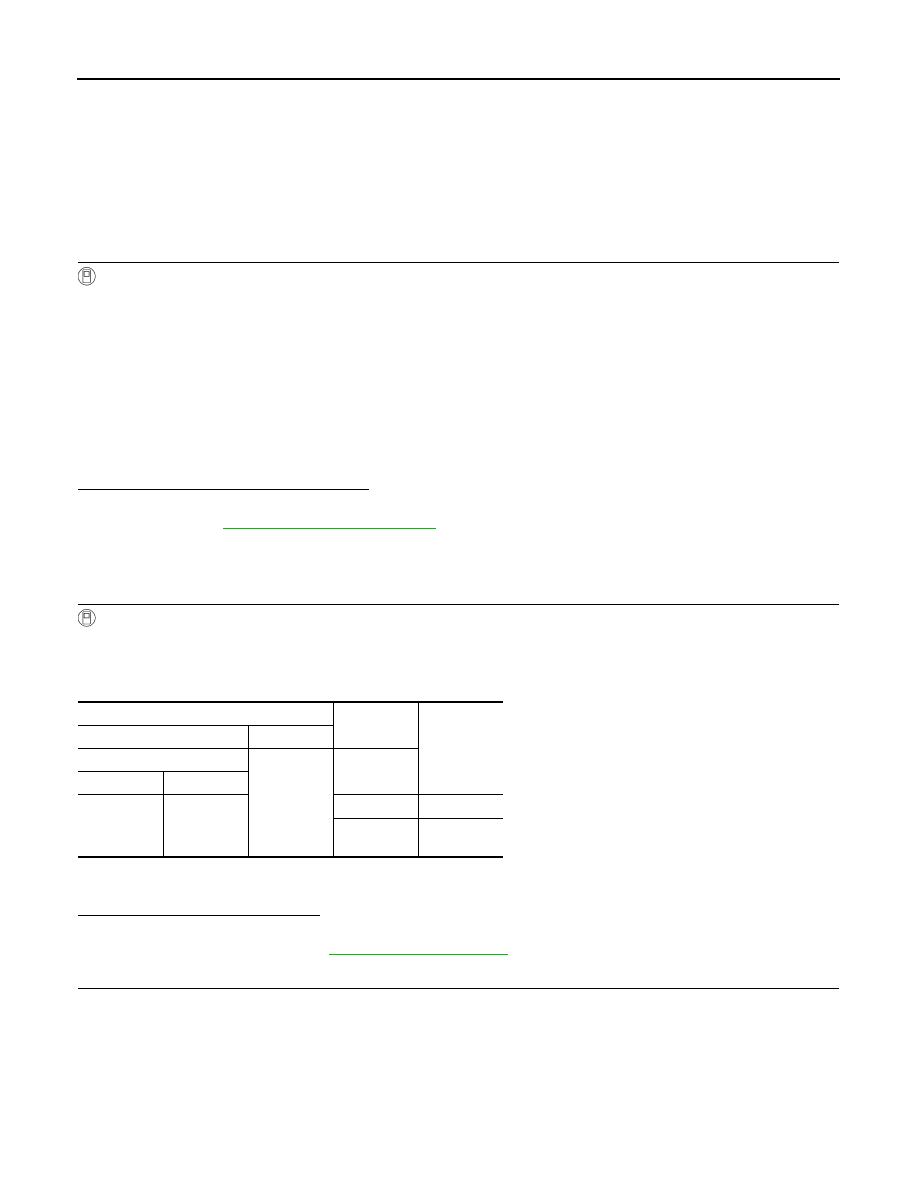
With operating the test item, check voltage between BCM harness connector and ground.

*1: With Intelligent Key

*2: Without Intelligent Key

Is the measurement value normal?

YES

>> GO TO 2.

NO

>> Replace BCM. Refer to 

BCS-88, "Exploded View"

.

2.

CHECK INTERIOR ROOM LAMP POWER SUPPLY OPEN CIRCUIT

1.

Turn ignition switch OFF.

2.

Disconnect the following connectors.

-

Map lamp

-

Room lamp

-

Luggage room lamp 

3.

Check continuity between BCM harness connector and each interior room lamp harness connector.

Off

: Interior room lamp OFF

On

: Interior room lamp ON

Terminals

Test item

Voltage (Ap-

prox.)

(+)

(

)

BCM

Ground

BATTERY 

SAVER

Connector

Terminal

M70

*1

M67

*2

56

Off

0 V

On

Battery volt-

age

INTERIOR ROOM LAMP POWER SUPPLY CIRCUIT

INL-25

< DTC/CIRCUIT DIAGNOSIS >

C

D

E

F

G

H

I

J

K

M

A

B

INL

N

O

P

*1: With Intelligent Key

*2: Without Intelligent Key

Does continuity exist?

YES

>> GO TO 3.

NO

>> Repair the harnesses or connectors.

3.

CHECK INTERIOR ROOM LAMP POWER SUPPLY SHORT CIRCUIT

Check continuity between BCM harness connector and ground.

*1: With Intelligent Key

*2: Without Intelligent Key

Does continuity exist?

YES

>> Repair the harnesses or connectors.

NO

>> Check that each interior room lamp has no internal short circuit.

BCM

Each interior room lamp

Continu-

ity

Connec-

tor

Terminal

Connector

Terminal

M70

*1

M67

*2

56

Map lamp

R4

4

Existed

Room lamp

R6

1

Luggage room lamp

B11

1

BCM

Ground

Continuity

Connector

Terminal

M70

*1

M67

*2

56

Not existed

INL-26

< DTC/CIRCUIT DIAGNOSIS >

INTERIOR ROOM LAMP CONTROL CIRCUIT

INTERIOR ROOM LAMP CONTROL CIRCUIT

Description

INFOID:0000000009950935

Controls each interior room lamp (ground side) by PWM signal.
NOTE:
PWM signal control period is approximately 250 Hz (in the gradual brightening/dimming).

Component Function Check

INFOID:0000000009950936

CAUTION:

 Before the diagnosis, check that the following items are normal.
• Interior room lamp power supply
• Map lamp bulb
• Room lamp bulb

1.

CHECK INTERIOR ROOM LAMP CONTROL FUNCTION

CONSULT ACTIVE TEST

1.

Switch the map lamp switch to DOOR.

2.

Turn ignition switch ON.

3.

Select “INT LAMP” of BCM (INT LAMP) active test item.

4.

With operating the test items, check that each interior room lamp turns ON/OFF (gradual brightening/dim-
ming).

Does the interior room lamp turns ON/OFF (gradual brightening/dimming)?

YES

>> Interior room lamp control circuit is normal.

NO

>> Refer to 

INL-26, "Diagnosis Procedure"

.

Diagnosis Procedure

INFOID:0000000009950937

1.

CHECK INTERIOR ROOM LAMP CONTROL OUTPUT

CONSULT ACTIVE TEST

1.

Turn ignition switch OFF.

2.

Remove all the bulbs of following lamps.

-

Map lamp

-

Room lamp

3.

Select “INT LAMP” of BCM (INT LAMP) active test item.

4.

 With operating the test item, check continuity between BCM harness connector and ground.

*1: With Intelligent Key

*2: Without Intelligent Key

Is the measurement value normal?

YES

>> GO TO 2.

Fixed ON>>GO TO 3.
Fixed OFF>>Replace BCM. Refer to 

BCS-88, "Exploded View"

.

2.

CHECK INTERIOR ROOM LAMP CONTROL OPEN CIRCUIT

1.

Turn ignition switch OFF.

2.

Disconnect the following connectors.

On

: Interior room lamp gradual 
brightening

Off

: Interior room lamp gradual dim-
ming

BCM

Ground

Test item

Continuity

Connector

Terminal

INT LAMP

M70

*1

M67

*2

63

On

Existed

Off

Not existed

INTERIOR ROOM LAMP CONTROL CIRCUIT

INL-27

< DTC/CIRCUIT DIAGNOSIS >

C

D

E

F

G

H

I

J

K

M

A

B

INL

N

O

P

-

Map lamp

-

Room lamp

3.

Check continuity between BCM harness connector, map lamp harness connector, and room lamp harness
connector.

*1: With Intelligent Key

*2: Without Intelligent Key

Does continuity exist?

YES

>> Replace the map lamp or the room lamp.

NO

>> Repair the harnesses or connectors.

3.

CHECK INTERIOR ROOM LAMP CONTROL SHORT CIRCUIT

1.

Turn ignition switch OFF.

2.

Disconnect BCM connector, map lamp connector and room lamp connector.

3.

Check continuity between BCM harness connector and ground.

*1: With Intelligent Key

*2: Without Intelligent Key

Does continuity exist?

YES

>> Repair the harnesses or connectors.

NO

>> Replace BCM. Refer to 

BCS-88, "Exploded View"

.

BCM

Map lamp/room lamp

Continuity

Connec-

tor

Terminal

Connector

Terminal

M70

*1

M67

*2

63

Map lamp

R4

2

Existed

Room lamp

R6

2

BCM

Ground

Continuity

Connector

Terminal

M70

*1

M67

*2

63

Not existed


Content   ..  599  600  601  602   ..