Nissan Cube. Manual - part 497


  Index      Nissan     Nissan Cube (2014 year) - Service and Repair Manual


Search            


Content   ..  495  496  497  498   ..


Nissan Cube. Manual - part 497


FAX-24

< REMOVAL AND INSTALLATION >

FRONT DRIVE SHAFT

c.

Install snap ring (1).

CAUTION:

Never reuse snap ring.

d.

Install dust shields.

CAUTION:

Never reuse dust shields.
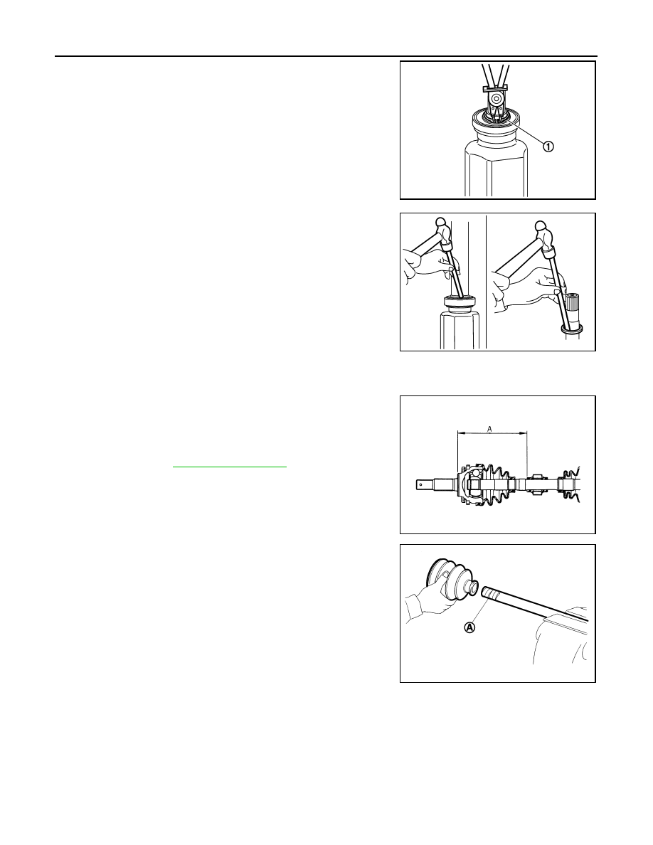
2.

Install dynamic damper, follow the procedure described below. 

a.

Install dynamic damper to shaft.

b.

Secure dynamic damper with bands in the following specified
position (A) when installing.

CAUTION:

Never reuse bands.

3.

Wrap serration on shaft with tape (A) to protect boot from dam-
age. Install new boot and boot bands to shaft.

CAUTION:

Never reuse boot and boot band. 

4.

Remove the tape wrapped around the serration on shaft.

JPDIF0106ZZ

JPDIF0127ZZ

: Refer to 

FAX-27, "Drive Shaft"

.

JPDIF0178ZZ

JPDIF0009ZZ

FRONT DRIVE SHAFT

FAX-25

< REMOVAL AND INSTALLATION >

C

E

F

G

H

I

J

K

L

M

A

B

FAX

N

O

P

5.

To install the spider assembly (1), align it with the matching
marks (A) on the shaft (2) during the removal, and direct the ser-
ration mounting surface (B) to the shaft.

6.

Secure spider assembly onto shaft with snap ring (1).

CAUTION:

Never reuse snap ring.

7.

Apply the appropriate amount of grease to spider assembly and
sliding surface.

8.

Assemble the housing onto spider assembly, and apply the bal-
ance of the specified amount grease.

9.

Align matching marks put during the removal of housing.

10. Install the boot, following the procedures below.

• Install boot securely into grooves (indicated by “*” marks)

shown in the figure (Except for CVT models).

CAUTION:

If grease adheres to the boot mounting surface (with “*”
mark) on shaft or housing, boot may be removed. Remove
all grease from the surface.

• Install boot securely into grooves (indicated by “*” marks)

shown in the figure (For CVT models).

CAUTION:

If grease adheres to the boot mounting surface (with “*”
mark) on shaft or housing, boot may be removed. Remove
all grease from the surface.

11. To prevent the deformation of the boot, adjust the boot installa-

tion length to the value shown below (L) by inserting the suitable
tool into the inside of boot from the large diameter side of boot
and discharging inside air.

CAUTION:

• If the boot installation length exceeds the standard, it may cause breakage of the boot.
• Be careful not to touch the inside of the boot with the tip of tool.

12. Secure housing and shaft, and then check that they are in the correct position when rotating boot. Install

them with new boot band when the mounting positions become incorrect.

Inspection

INFOID:0000000009948803

INSPECTION AFTER REMOVAL

Check the following items, and replace the part if necessary.

JPDIF0017ZZ

Grease amount

: Refer to 

FAX-27, "Drive Shaft"

.

JPDIF0014ZZ

JPDIF0224ZZ

L

: Refer to 

FAX-27, "Drive Shaft"

.

JPDIF0144ZZ

FAX-26

< REMOVAL AND INSTALLATION >

FRONT DRIVE SHAFT

• Move joint up/down, left/right, and in the axial directions. Check for motion that is not smooth and for signifi-

cant looseness.

• Check boot for cracks, damage, and leakage of grease.
• Check the support bearing bracket for cracks, deformation and other damage.

INSPECTION AFTER DISASSEMBLY

Check the following items, and replace the part if necessary.

Shaft

Check shaft for runout, cracks, or other damage. Replace if necessary.

Dynamic Damper

Check damper for cracks or wear. Replace if necessary.

Joint Sub-Assembly (Wheel Side)

Check the following:
• Joint sub-assembly for rough rotation and excessive axial looseness.
• The inside of the joint sub-assembly for entry of foreign material.
• Joint sub-assembly for compression scars, cracks, and fractures inside of joint sub-assembly.
Replace joint sub-assembly if there are any non-standard conditions of components.

Housing and spider assembly (Transaxle Side)

Replace housing and spider assembly if there is scratching or wear of housing roller contact surface or spider
roller contact surface.
NOTE:
Housing and spider assembly are used in a set.

Support Bearing (Right Side)

Check bearing rolls freely and is free from noise, cracks, pitting or wear. Replace support bearing if there are
any non-standard conditions.

Support Bearing Bracket (Right Side)

Check for support bearing bracket, cracks, or damage. Replace support bearing bracket if there are any non-
standard conditions.

INSPECTION AFTER INSTALLATION

1.

Check wheel sensor harness for proper connection. Refer to 

BRC-110, "FRONT WHEEL SENSOR :

Exploded View"

2.

Adjust neutral position of steering angle sensor. Refer to 

BRC-9, "Special Repair Requirement"

.

SERVICE DATA AND SPECIFICATIONS (SDS)

FAX-27

< SERVICE DATA AND SPECIFICATIONS (SDS) 

C

E

F

G

H

I

J

K

L

M

A

B

FAX

N

O

P

SERVICE DATA AND SPECIFICATIONS (SDS)

SERVICE DATA AND SPECIFICATIONS (SDS)

Wheel Bearing

INFOID:0000000009948804

Drive Shaft

INFOID:0000000009948805

Item

Standard

Axial end play

0.05 mm (0.002 in) or less

Item

Left side

Right side

Grease quantity

Wheel side

MT

80 – 100 g (2.83 – 3.52 oz)

CVT

77 – 97 g (2.72 – 3.42 oz)

Transaxle side

MT

130 – 140 g (4.59 – 4.93 oz)

CVT

113 – 123 g (3.99 – 4.33 oz)

Boots installed length

Wheel side

MT

141.7 mm (5.58 in)

CVT

136.0 mm (5.35 in)

Transaxle side

MT

155.7 mm (6.13 in)

167.7 mm (6.60 in)

CVT

153.6 mm (6.05 in)

148.6 mm (5.85 in)

Dimension of dynamic damper

MT

230 – 236 mm (9.06 – 9.29 in)

CVT

225 – 231 mm (8.86 – 9.09 in)


Content   ..  495  496  497  498   ..