Nissan Cube. Manual - part 496
FAX-20
< REMOVAL AND INSTALLATION >
FRONT DRIVE SHAFT
TRANSAXLE SIDE : Disassembly and Assembly
INFOID:0000000009948802
DISASSEMBLY
Left Side
1.
Fix shaft with a vise.
CAUTION:
Protect shaft using aluminum or copper plates when fixing with a vise.
2.
Remove boot bands, and then remove boot from housing.
3.
Put matching marks on housing and shaft, and then pull out housing from shaft.
CAUTION:
Use paint or an equivalent for matching marks. Never scratch the surfaces.
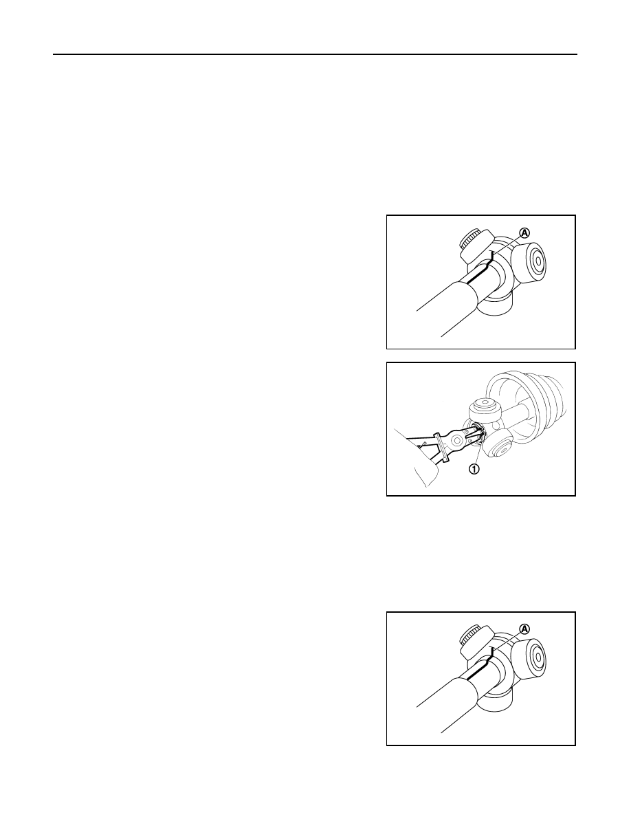
4.
Put matching marks (A) on the spider assembly and shaft.
CAUTION:
Use paint or an equivalent for matching marks. Never
scratch the surfaces.
5.
Remove snap ring (1), and then remove spider assembly from
shaft.
6.
Remove boot from shaft.
7.
Remove dust shield from housing.
8.
Remove circular clip from housing.
9.
Clean old grease on housing with paper towels.
10. Remove damper bands, then remove dynamic damper from
shaft.
Right Side
1.
Fix shaft with a vise.
CAUTION:
Protect shaft using aluminum or copper plates when fixing with a vise.
2.
Remove boot bands, and then remove boot from housing.
3.
Put matching marks on housing and shaft, and then pull out housing from shaft.
CAUTION:
Use paint or an equivalent for matching marks. Never scratch the surfaces.
4.
Put matching marks (A) on the spider assembly and shaft.
CAUTION:
Use paint or an equivalent for matching marks. Never
scratch the surfaces.
JPDIF0006ZZ
JPDIF0014ZZ
JPDIF0006ZZ