Nissan Cube. Manual - part 495


  Index      Nissan     Nissan Cube (2014 year) - Service and Repair Manual


Search            


Content   ..  493  494  495  496   ..


Nissan Cube. Manual - part 495


FAX-16

< REMOVAL AND INSTALLATION >

FRONT DRIVE SHAFT

LEFT SIDE

LEFT SIDE : Removal and Installation

INFOID:0000000009948799

REMOVAL

1.

Remove tires with power tool. Refer to 

WT-46, "Exploded View"

.

2.

Remove cotter pin, and then loosen wheel hub lock nut. Refer to 

FAX-9, "Exploded View"

.

3.

Patch wheel hub lock nut with a piece of wood. Hammer the wood to disengage wheel hub and bearing
assembly from drive shaft.

CAUTION:

• Never place drive shaft joint at an extreme angle. Also be careful not to overextend slide joint.
• Never allow drive shaft to hang down without support for joint sub-assembly, shaft and the other

parts.

NOTE:
Use suitable puller, if wheel hub and bearing assembly and drive shaft cannot be separated even after
performing the above procedure.

4.

Remove wheel hub lock nut.

5.

Remove transverse link from steering knuckle. Refer to 

FSU-13, "Exploded View"

.

6.

Remove shaft assembly from wheel hub and bearing assembly.

CAUTION:

Be careful not to damage front wheel sensor and harness.
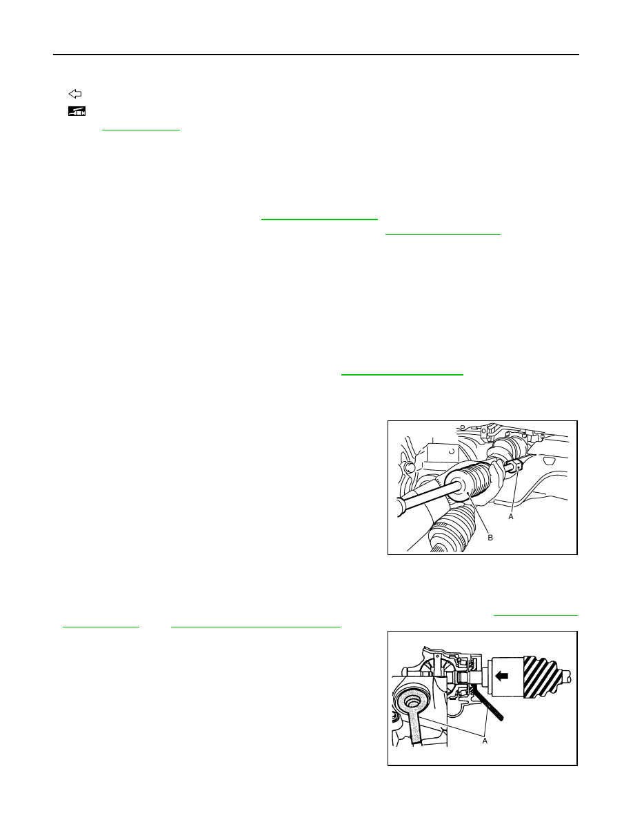
7.

Use the drive shaft attachment [SST: KV40107500 (

)] (A)

and a sliding hammer (commercial service tool) (B) while insert-
ing tip of the drive shaft attachment between shaft and transaxle
assembly, and then remove drive shaft from transaxle assembly.

CAUTION:

• Never place drive shaft joint at an extreme angle when

removing drive shaft. Also be careful not to overextend
slide joint.

• Confirm that the circular clip is attached to the drive shaft.

INSTALLATION

Note the following, and install in the reverse order of removal.

Transaxle Side

• Always replace differential side oil seal with new one when installing drive shaft. Refer to 

TM-18, "Removal

and Installation"

 (MT), 

TM-229, "Removal and Installation"

 (CVT).

• Place the protector [SST: KV38107900 (

)] (A) onto transaxle

assembly to prevent damage to the oil seal while inserting drive
shaft. Slide drive shaft sliding joint and tap with a hammer to install
securely.

CAUTION:

Check that circular clip is completely engaged.

Wheel Hub Side

13. Snap ring

14. Dust shield

15. Plate

16. Support bearing bracket

: Wheel side

: Fill NISSAN Genuine grease or equivalent.

Refer to 

GI-4, "Components"

 for symbols not described on the above.

JPDIF0004ZZ

JPDIF0023ZZ

FRONT DRIVE SHAFT

FAX-17

< REMOVAL AND INSTALLATION >

C

E

F

G

H

I

J

K

L

M

A

B

FAX

N

O

P

• Clean the matching surface of wheel hub lock nut and wheel hub and bearing assembly.

CAUTION:

Never apply lubricating oil to these matching surface.

• Tighten the wheel hub lock nut to the specified torque. Refer to 

FAX-9, "Exploded View"

.

CAUTION:

Never use a power tool to tighten the wheel hub lock nut.

• Perform the final tightening of each of parts under unladen conditions, which were removed when removing

wheel hub and bearing assembly and axle housing. 

• Never reuse cotter pin.

RIGHT SIDE

RIGHT SIDE : Removal and Installation

INFOID:0000000009948800

REMOVAL

1.

Remove tires with power tool. Refer to 

WT-46, "Exploded View"

.

2.

Remove wheel sensor and sensor harness if necessary. Refer to 

BRC-110, "FRONT WHEEL SENSOR :

Exploded View"

.

3.

Remove cotter pin, and then loosen wheel hub lock nut. Refer to 

FAX-9, "Exploded View"

.

4.

Patch wheel hub lock nut with a piece of wood. Hammer the wood to disengage wheel hub and bearing
assembly from drive shaft.

CAUTION:

• Never place drive shaft joint at an extreme angle. Also be careful not to overextend slide joint.
• Never allow drive shaft to hang down without support for joint sub-assembly, shaft and the other

parts.

NOTE:
Use suitable puller, if wheel hub and bearing assembly and drive shaft cannot be separated even after
performing the above procedure.

5.

Remove wheel hub lock nut.

6.

Remove transverse link from steering knuckle. Refer to 

FSU-13, "Exploded View"

.

7.

Remove drive shaft from wheel hub and bearing assembly.

8.

Remove bearing housing plate bolts.

9.

Remove drive shaft from transaxle assembly.

CAUTION:

Never place drive shaft joint at an extreme angle when removing drive shaft. Also be careful not to
overextend slide joint.

10. Remove support bearing bracket.

INSTALLATION

Note the following, and install in the reverse order of removal.

Transaxle Side

• Always replace differential side oil seal with new one when installing drive shaft. Refer to 

TM-18, "Removal

and Installation"

 (MT), 

TM-229, "Removal and Installation"

 (CVT).

• Install support bearing bracket (1) in following procedure,
- Temporarily tighten mounting bolts (A), (B), then tighten them to

specified torque. 

- Set plate (2) so that notch (C) becomes upper side. Temporarily

tighten mounting bolts (a), (b), then tighten them to specified
torque.

CAUTION:

Never reuse plate.

SDIA3224J

FAX-18

< REMOVAL AND INSTALLATION >

FRONT DRIVE SHAFT

• Place the protector [SST: KV38107900 (

)] (A) onto transaxle

assembly to prevent damage to the oil seal while inserting drive
shaft. Slide drive shaft sliding joint and tap with a hammer to install
securely.

Wheel Hub Side

• Clean the matching surface of wheel hub lock nut and wheel hub and bearing assembly.

CAUTION:

Never apply lubricating oil to these matching surface.

• Tighten the wheel hub lock nut to the specified torque. Refer to 

FAX-9, "Exploded View"

.

CAUTION:

Never use a power tool to tighten the wheel hub lock nut.

• Perform the final tightening of each of parts under unladen conditions, which were removed when removing

wheel hub and bearing assembly and axle housing. 

• Never reuse cotter pin.

WHEEL SIDE

WHEEL SIDE : Disassembly and Assembly

INFOID:0000000009948801

DISASSEMBLY

1.

Fix shaft with a vise.

CAUTION:

Protect shaft when fixing with a vise using aluminum or copper plates.

2.

Remove boot bands, and then remove boot from joint sub-assembly.

3.

Screw drive shaft puller (commercial service tool) (A) into joint
sub-assembly screw part to a length of 30 mm (1.18 in) or more.
Support drive shaft with one hand and pull out joint sub-assem-
bly from shaft.

CAUTION:

• Align a sliding hammer and drive shaft and remove them

by pulling firmly and uniformly.

• If joint sub-assembly cannot be pulled out, try after

removing drive shaft from vehicle.

4.

Remove circular clip (1) from shaft.

5.

Remove boot from shaft.

ASSEMBLY

1.

Clean the old grease on joint sub-assembly with paper waste.

2.

Fill serration slot joint sub-assembly with NISSAN genuine grease or equivalent until the serration slot and
ball groove become full to the brim.

CAUTION:

After applying grease, use a paper waste to wipe off old grease that has oozed out.

3.

Install boot and boot bands to shaft.

CAUTION:

• Wrap serration on shaft with tape to protect the boot from damage.
• Never reuse boot and boot band.

4.

Remove the tape wrapped around the serration on shaft.

5.

Position the circular clip on groove at the shaft edge.

CAUTION:

Never reuse circular clip.
NOTE:

JPDIF0049ZZ

JPDIG0151ZZ

FRONT DRIVE SHAFT

FAX-19

< REMOVAL AND INSTALLATION >

C

E

F

G

H

I

J

K

L

M

A

B

FAX

N

O

P

Drive joint inserter is recommended when installing circular clip.

6.

Align both center axles of the shaft edge and joint sub-assembly. Then assemble shaft with joint sub-
assembly holding circular clip.

7.

Install joint sub-assembly to shaft using plastic hammer.

CAUTION:

• Check circular clip is properly positioned on groove of the

joint sub-assembly.

• Confirm that joint sub-assembly is correctly engaged

while rotating drive shaft.

8.

Apply the specified amount of grease into the boot inside from
large diameter side of boot.

9.

Install the boot securely into grooves (indicated by “*” marks)
shown in the figure.

CAUTION:

If grease adheres to the boot mounting surface (indicated
by “*” mark) on the shaft or joint sub-assembly, boot may
be removed. Remove all grease from the boot mounting
surface.

10. To prevent the deformation of the boot, adjust the boot installa-

tion length (L) to the specified value shown below by inserting
the suitable tool into inside of the boot from the large diameter
side of the boot and discharging the inside air.

CAUTION:

• If the boot installation length exceeds the standard, it may cause breakage of the boot.
• Be careful not to touch the inside of the boot with a tip of tool.

11. Secure the large and small ends of the boot with boot bands

using the boot band crimping tool [SST: KV40107300 (

)]

(A).

CAUTION:

Never reuse boot band.

NOTE:
Secure boot band so that dimension (A) meets the specification
as shown in the figure.

12. Secure joint sub-assembly and shaft, and then check that they

are in the correct position when rotating boot. Reinstall them
using boot bands when boot installation positions become incor-
rect.

CAUTION:

Never reuse boot band.

TRANSAXLE SIDE

Grease amount

: Refer to 

FAX-27, "Drive Shaft"

.

RAC0049D

L

: Refer to 

FAX-27, "Drive Shaft"

.

JPDIF0222ZZ

JPDIF0012ZZ

A

: 7.0 mm (0.276 in) or less

JPDIF0268ZZ


Content   ..  493  494  495  496   ..