Nissan Cube. Manual - part 250


  Index      Nissan     Nissan Cube (2014 year) - Service and Repair Manual


Search            


Content   ..  248  249  250  251   ..


Nissan Cube. Manual - part 250


DLK-266

< DTC/CIRCUIT DIAGNOSIS >

[WITHOUT INTELLIGENT KEY SYSTEM]

REMOTE KEYLESS ENTRY RECEIVER

3.

Check continuity between BCM harness connector and ground.

Is the inspection result normal?

YES

>> Replace BCM. Refer to 

BCS-155, "Removal and Installation"

.

NO

>> Repair or replace harness.

7.

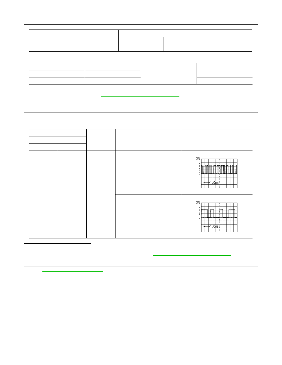
CHECK REMOTE KEYLESS ENTRY RECEIVER SIGNAL

1.

Reconnect remote keyless entry receiver connector.

2.

Check signal between remote keyless entry receiver harness connector and ground using oscilloscope.

Is the inspection result normal?

YES

>> GO TO 8.

NO

>> Replace remote keyless entry receiver. Refer to 

DLK-379, "Removal and Installation"

.

8.

CHECK INTERMITTENT INCIDENT

Refer to 

GI-40, "Intermittent Incident"

.

>> INSPECTION END 

BCM

Remote keyless entry receiver

Continuity 

Connector

Terminal

Connector

Terminal

M65

20

M61

2

Existed

BCM

Ground

Continuity 

Connector

Terminal

M65

20

Not existed

(+)

(–)

Condition

Signal

(Reference value)

Remote keyless entry receiver

Connector

Terminal

M61

2

Ground

Waiting

Signal receiving

PIIB7728J

PIIB7729J

KEY SWITCH

DLK-267

< DTC/CIRCUIT DIAGNOSIS >

[WITHOUT INTELLIGENT KEY SYSTEM]

C

D

E

F

G

H

I

J

L

M

A

B

DLK

N

O

P

KEY SWITCH

Description

INFOID:0000000009950723

Key switch detects that ignition key is inserted into the key cylinder, and then transmits the signal to BCM. 

Component Function Check

INFOID:0000000009950724

1.

CHECK FUNCTION

Check (“KEY ON SW”) in BCM “DATA MONITOR” mode using CONSULT..

Is the inspection result normal?

YES

>> Key switch is OK.

NO

>> Refer to 

DLK-267, "Diagnosis Procedure"

.

Diagnosis Procedure

INFOID:0000000009950725

1.

CHECK FUSE

1.

Turn ignition switch OFF.

2.

Check 10 A fuse, [No.10, located in fuse block (J/B)].

Is fuse fusing?

YES

>> Replace the blown fuse after repairing the affected circuit if a fuse is blown.

NO

>> GO TO 2.

2.

CHECK KEY SWITCH POWER SUPPLY CIRCUIT

1.

Disconnect key switch connector.

2.

Check voltage between key switch harness connector and ground.

Is the inspection result normal?

YES

>> GO TO 3.

NO

>> Repair or replace harness.

3.

CHECK KEY SWITCH CIRCUIT

1.

Disconnect BCM connector.

2.

Check continuity between key switch harness connector and BCM harness connector.

3.

Check continuity between key switch connector and ground.

Is the inspection result normal?

YES

>> GO TO 4

NO

>> Repair or replace harness.

Monitor item

Condition

Status

KEY ON SW

Keyfob

Inserted in key cylinder

ON

Removed from key cylinder

OFF

Key switch

Ground

Voltage (V) 

(Approx.)

Connector

Terminal

M24

2

Battery voltage

Key switch

BCM

Continuity

Connector

Terminal

Connector

Terminal

M24

1

M65

37

Existed

Key switch

Ground

Continuity 

Connector

Terminal

M24

1

Not existed

DLK-268

< DTC/CIRCUIT DIAGNOSIS >

[WITHOUT INTELLIGENT KEY SYSTEM]

KEY SWITCH

4.

CHECK KEY SWITCH

Refer to 

DLK-268, "Component Inspection"

.

Is the inspection result normal?

YES

>> GO TO 5.

NO

>> Replace key switch.

5.

CHECK INTERMITTENT INCIDENT

Refer to 

GI-40, "Intermittent Incident"

.

>> INSPECTION END

Component Inspection

INFOID:0000000009950726

COMPONENT INSPECTION

1.

CHECK KEY SWITCH

1.

Turn ignition switch OFF.

2.

Disconnect key switch connector.

3.

Check continuity between key switch terminals.

Is the inspection result normal?

YES

>> INSPECTION END

NO

>> Replace key switch.

Key switch

Condition

Continuity

Terminal

1

2

Keyfob

Inserted in key cylinder

Existed

Removed from key cylinder

Not existed

BUZZER (COMBINATION METER)

DLK-269

< DTC/CIRCUIT DIAGNOSIS >

[WITHOUT INTELLIGENT KEY SYSTEM]

C

D

E

F

G

H

I

J

L

M

A

B

DLK

N

O

P

BUZZER (COMBINATION METER)

Description

INFOID:0000000009950727

Performs operation method guide and warning with buzzer.

Component Function Check

INFOID:0000000009950728

1.

CHECK FUNCTION

1.

Check the operation with “INSIDE BUZZER” in the Active Test.

2.

Touch “take out”, “knob”or “key”on screen.

Is the inspection result normal?

Yes

>> Buzzer (combination meter) is OK.

No

>> Refer to 

DLK-269, "Diagnosis Procedure"

.

Diagnosis Procedure

INFOID:0000000009950729

1.

CHECK METER BUZZER CIRCUIT

Refer to 

WCS-25, "Component Function Check"

.

Is the inspection result normal?

Yes

>> GO TO 2.

No

>> Repair or replace meter buzzer circuit.

2.

CHECK INTERMITTENT INCIDENT

Refer to 

GI-40, "Intermittent Incident"

.

>> INSPECTION END


Content   ..  248  249  250  251   ..