Nissan Cube. Manual - part 249
DLK-262
< DTC/CIRCUIT DIAGNOSIS >
[WITHOUT INTELLIGENT KEY SYSTEM]
DOOR KEY CYLINDER SWITCH
DOOR KEY CYLINDER SWITCH
Description
INFOID:0000000009950716
Transmits lock/unlock operation to BCM.
Component Function Check
INFOID:0000000009950717
1.
CHECK DOOR KEY CYLINDER SWITCH INPUT SIGNAL
Check (“KEY CYL LK-SW”, “KEY CYL UN-SW”) in “Data Monitor” mode using CONSULT.
Is the inspection result normal?
YES
>> Door key cylinder switch is OK.
NO
>> Refer to
DLK-262, "Diagnosis Procedure"
.
Diagnosis Procedure
INFOID:0000000009950718
1.
CHECK DOOR KEY CYLINDER SWITCH INPUT SIGNAL
1.
Turn ignition switch OFF.
2.
Disconnect front door lock assembly (driver side) connector.
3.
Check voltage between front door lock assembly (driver side) harness connector and ground.
Is the inspection result normal?
YES
>> GO TO 3.
NO
>> GO TO 2.
2.
CHECK DOOR KEY CYLINDER SWITCH SIGNAL CIRCUIT
1.
Disconnect BCM connector.
2.
Check continuity between BCM harness connector and front door lock assembly (driver side) harness
connector.
Monitor item
Condition
Status
KEY CYL LK-SW
Driver side door key cylinder
Lock
ON
Neutral / Unlock
OFF
KEY CYL UN-SW
Unlock
ON
Neutral / Lock
OFF
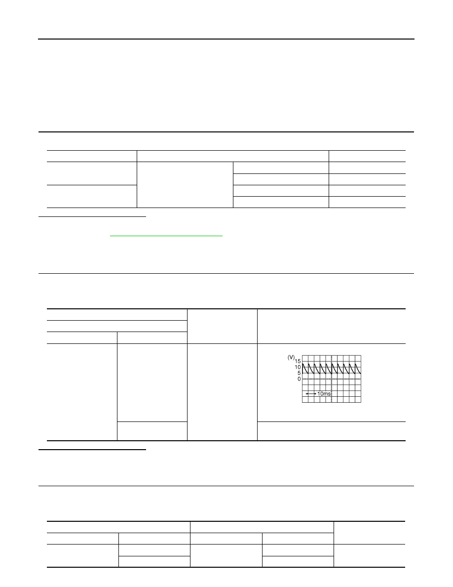
(+)
(–)
Voltage (V)
(Approx.)
Front door lock assembly (driver side)
Connector
Terminal
D9
5
Ground
8.0 - 8.5 V
6
Battery voltage
JPMIA0587GB
BCM
Front door lock assembly (driver side)
Continuity
Connector
Terminal
Connector
Terminal
M65
7
D9
5
Existed
8
6