Nissan Cube. Manual - part 248


  Index      Nissan     Nissan Cube (2014 year) - Service and Repair Manual


Search            


Content   ..  246  247  248  249   ..


Nissan Cube. Manual - part 248


DLK-258

< DTC/CIRCUIT DIAGNOSIS >

[WITHOUT INTELLIGENT KEY SYSTEM]

DOOR LOCK ACTUATOR

PASSENGER SIDE : Description

INFOID:0000000009950704

Locks/unlocks the door with the signal from BCM.

PASSENGER SIDE : Component Function Check

INFOID:0000000009950705

1.

CHECK FUNCTION

1.

Use CONSULT to perform Active Test (“DOOR LOCK”).

2.

Touch “ALL LOCK” or “ALL UNLK” to check that it works normally.

Is the inspection result normal?

YES

>> Door lock actuator is OK.

NO

>> Refer to 

DLK-258, "PASSENGER SIDE : Diagnosis Procedure"

.

PASSENGER SIDE : Diagnosis Procedure

INFOID:0000000009950706

1.

CHECK DOOR LOCK ACTUATOR INPUT SIGNAL

1.

Turn ignition switch OFF.

2.

Disconnect front door lock assembly (passenger side) connector.

3.

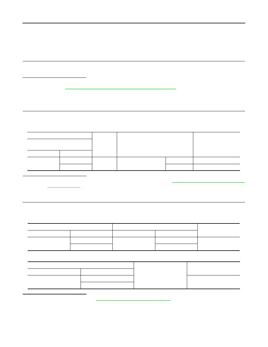
Check voltage between front door lock assembly (passenger side) harness connector and ground.

Is the inspection result normal?

YES

>> Replace front door lock assembly (passenger side). Refer to 

DLK-365, "DOOR LOCK : Removal

and Installation"

.

NO

>> GO TO 2.

2.

CHECK DOOR LOCK ACTUATOR CIRCUIT

1.

Disconnect BCM connector and all door lock actuator connector. 

2.

Check continuity between BCM harness connector and front door lock assembly (passenger side) har-
ness connector. 

3.

Check continuity between BCM harness connector and ground.

Is the inspection result normal?

YES

>> Replace BCM. Refer to 

BCS-155, "Removal and Installation"

.

NO

>> Repair or replace harness.

REAR LH

REAR LH : Description

INFOID:0000000009950707

Locks/unlocks the door with the signal from BCM.

(+)

(–)

Condition

Voltage (V)

(Approx.)

Front door lock assembly

(passenger side)

Connector

Terminal

D28

5

Ground

Door lock and unlock switch

Lock

 Battery voltage 

 0

6

Unlock

 Battery voltage 

 0

BCM

Front door lock assembly (passenger side)

Continuity 

Connector

Terminal

Connector

Terminal

M67

65

D28

5

Existed

66

6

BCM

Ground

Continuity 

Connector

Terminal

M67

65

Not existed

66

DOOR LOCK ACTUATOR

DLK-259

< DTC/CIRCUIT DIAGNOSIS >

[WITHOUT INTELLIGENT KEY SYSTEM]

C

D

E

F

G

H

I

J

L

M

A

B

DLK

N

O

P

REAR LH : Component Function Check

INFOID:0000000009950708

1.

CHECK FUNCTION

1.

Use CONSULT to perform Active Test (“DOOR LOCK”).

2.

Touch “ALL LOCK” or “ALL UNLK” to check that it works normally.

Is the inspection result normal?

YES

>> Door lock actuator is OK.

NO

>> Refer to 

DLK-260, "REAR RH : Diagnosis Procedure"

.

REAR LH : Diagnosis Procedure

INFOID:0000000009950709

1.

CHECK DOOR LOCK ACTUATOR INPUT SIGNAL

1.

Turn ignition switch OFF.

2.

Disconnect rear door lock assembly LH connector.

3.

Check voltage between rear door lock assembly LH harness connector and ground.

Is the inspection result normal?

YES

>> Replace rear door lock assembly LH. Refer to 

DLK-369, "DOOR LOCK : Removal and Installa-

tion"

.

NO

>> GO TO 2.

2.

CHECK DOOR LOCK ACTUATOR CIRCUIT

1.

Disconnect BCM connector and all door lock actuator.

2.

Check continuity between BCM harness connector and rear door lock assembly LH harness connector. 

3.

Check continuity between BCM harness connector and ground.

Is the inspection result normal?

YES

>> Replace BCM. Refer to 

BCS-155, "Removal and Installation"

.

NO

>> Repair or replace harness.

REAR RH

REAR RH : Description

INFOID:0000000009950710

Locks/unlocks the door with the signal from BCM.

REAR RH : Component Function Check

INFOID:0000000009950711

1.

CHECK FUNCTION

1.

Use CONSULT to perform Active Test (“DOOR LOCK”).

(+)

(–)

Condition

Voltage (V)

(Approx.)

Rear door lock assembly LH

Connector

Terminal

D65

1

Ground

Door lock and unlock switch

Lock

 Battery voltage 

 0

2

Unlock

 Battery voltage 

 0

BCM

Rear door lock assembly LH

Continuity 

Connector

Terminal

Connector

Terminal

M67

65

D65

1

Existed

66

2

BCM

Ground

Continuity 

Connector

Terminal

M67

65

Not existed

66

DLK-260

< DTC/CIRCUIT DIAGNOSIS >

[WITHOUT INTELLIGENT KEY SYSTEM]

DOOR LOCK ACTUATOR

2.

Touch “ALL LOCK” or “ALL UNLK” to check that it works normally.

Is the inspection result normal?

YES

>> Door lock actuator is OK.

NO

>> Refer to 

DLK-260, "REAR RH : Diagnosis Procedure"

.

REAR RH : Diagnosis Procedure

INFOID:0000000009950712

1.

CHECK DOOR LOCK ACTUATOR INPUT SIGNAL

1.

Turn ignition switch OFF.

2.

Disconnect rear door lock assembly RH connector.

3.

Check voltage between rear door lock assembly RH harness connector and ground.

Is the inspection result normal?

YES

>> Replace rear door lock assembly RH. Refer to 

DLK-369, "DOOR LOCK : Removal and Installa-

tion"

.

NO

>> GO TO 2.

2.

CHECK DOOR LOCK ACTUATOR CIRCUIT

1.

Disconnect BCM connector and all door lock actuator.

2.

Check continuity between BCM harness connector and rear door lock assembly RH harness connector. 

3.

Check continuity between BCM harness connector and ground.

Is the inspection result normal?

YES

>> Replace BCM. Refer to 

BCS-155, "Removal and Installation"

.

NO

>> Repair or replace harness.

BACK DOOR

BACK DOOR : Description

INFOID:0000000009950713

Locks/unlocks the door with the signal from BCM.

BACK DOOR : Component Function Check

INFOID:0000000009950714

1.

CHECK FUNCTION

1.

Use CONSULT to perform Active Test (“DOOR LOCK”).

2.

Touch “ALL LOCK” or “ALL UNLK” to check that it works normally.

Is the inspection result normal?

YES

>> Back door lock actuator is OK.

NO

>> Refer to 

DLK-261, "BACK DOOR : Diagnosis Procedure"

.

(+)

(–)

Condition

Voltage (V)

(Approx.)

Rear door lock assembly RH

Connector

Terminal

D45

5

Ground

Door lock and unlock switch

Lock

 Battery voltage 

 0

6

Unlock

 Battery voltage 

 0

BCM

Rear door lock assembly RH

Continuity 

Connector

Terminal

Connector

Terminal

M67

65

D45

5

Existed

66

6

BCM

Ground

Continuity 

Connector

Terminal

M67

65

Not existed

66

DOOR LOCK ACTUATOR

DLK-261

< DTC/CIRCUIT DIAGNOSIS >

[WITHOUT INTELLIGENT KEY SYSTEM]

C

D

E

F

G

H

I

J

L

M

A

B

DLK

N

O

P

BACK DOOR : Diagnosis Procedure

INFOID:0000000009950715

1.

CHECK BACK DOOR LOCK ACTUATOR INPUT SIGNAL

1.

Turn ignition switch OFF.

2.

Disconnect back door lock assembly connector.

3.

Check voltage between back door lock assembly harness connector and ground.

Is the inspection result normal?

YES

>> Replace back door lock assembly. Refer to 

DLK-373, "DOOR LOCK : Removal and Installation"

.

NO

>> GO TO 2

2.

CHECK BACK DOOR LOCK ACTUATOR CIRCUIT

1.

Disconnect BCM connector and all door lock actuator.

2.

Check continuity between BCM harness connector and back door lock assembly harness connector. 

3.

Check continuity between BCM harness connector and ground.

Is the inspection result normal?

YES

>> Replace BCM. Refer to 

BCS-155, "Removal and Installation"

.

NO

>> Repair or replace harness.

(+)

(–)

Condition

Voltage (V)

(Approx.)

Back door lock assembly

Connector

Terminal

D106

2

Ground

Door lock and unlock switch

Unlock

 Battery voltage 

 0

3

Lock

 Battery voltage 

 0

BCM

Back door lock assembly

Continuity 

Connector

Terminal

Connector

Terminal

M67

65

D106

3

Existed

66

2

BCM

Ground

Continuity 

Connector

Terminal

M67

65

Not existed

66


Content   ..  246  247  248  249   ..