Nissan Cube. Manual - part 246


  Index      Nissan     Nissan Cube (2014 year) - Service and Repair Manual


Search            


Content   ..  244  245  246  247   ..


Nissan Cube. Manual - part 246


DLK-250

< DTC/CIRCUIT DIAGNOSIS >

[WITHOUT INTELLIGENT KEY SYSTEM]

DOOR SWITCH

Is the inspection result normal?

YES

>> GO TO 3.

NO

>> GO TO 2.

2.

CHECK DOOR SWITCH CIRCUIT 

1.

Disconnect BCM connector.

2.

Check continuity between door switch harness connector and BCM harness connector.
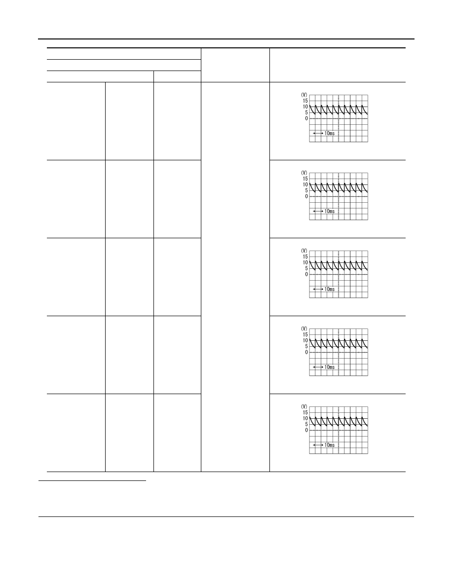
(+)

(–)

Signal

(Reference value)

Door switch

Connector

Terminal

Driver side

B34

3

Ground

7.0 - 8.0 V

Passenger side

B27

3

7.0 - 8.0 V

Rear LH

B71

3

7.0 - 8.0 V

Rear RH

B53

3

7.0 - 8.0 V

Back door

B75

3

9.5 - 10.0 V

PKIB4960J

PKIB4960J

PKIB4960J

PKIB4960J

PKIB4960J

DOOR SWITCH

DLK-251

< DTC/CIRCUIT DIAGNOSIS >

[WITHOUT INTELLIGENT KEY SYSTEM]

C

D

E

F

G

H

I

J

L

M

A

B

DLK

N

O

P

3.

Check continuity between door switch harness connector and ground.

Is the inspection result normal?

YES

>> Replace BCM. Refer to 

BCS-155, "Removal and Installation"

.

NO

>> Repair or replace harness.

3.

CHECK DOOR SWITCH 

Refer to 

DLK-251, "Component Inspection"

.

Is the inspection result normal?

YES

>> GO TO 4.

NO

>> Replace malfunctioning door switch. Refer to 

DLK-378, "Removal and Installation"

.

4.

CHECK INTERMITTENT INCIDENT

Refer to 

GI-40, "Intermittent Incident"

.

>> INSPECTION END 

Component Inspection

INFOID:0000000009950692

1.

CHECK DOOR SWITCH

1.

Turn ignition switch OFF.

2.

Disconnect malfunctioning door switch connector.

3.

Check continuity between door switch terminals.

Is the inspection result normal?

YES

>> INSPECTION END

NO

>> Replace malfunction door switch. Refer to 

DLK-378, "Removal and Installation"

.

Door switch

BCM

Continuity 

Connector

Terminal

Connector

Terminal

Driver side

B34

3

M66

47

Existed

Passenger side

B27

M65

12

Rear LH

B71

M66

48

Rear RH

B53

M65

13

Back door

B75

M66

43

Door switch

Ground

Continuity 

Connector

Terminal

Driver side

B34

3

Not existed

Passenger side

B27

Rear LH

B71

Rear RH

B53

Back door

B75

Door switch

Condition

Continuity

Terminal

3

Ground part of door switch

Door switch

Pressed

Not existed

Released

Existed

DLK-252

< DTC/CIRCUIT DIAGNOSIS >

[WITHOUT INTELLIGENT KEY SYSTEM]

DOOR LOCK AND UNLOCK SWITCH

DOOR LOCK AND UNLOCK SWITCH

DRIVER SIDE

DRIVER SIDE : Description

INFOID:0000000009950693

Transmits door lock/unlock operation to BCM.

DRIVER SIDE : Component Function Check

INFOID:0000000009950694

1.

CHECK FUNCTION

Check “CDL LOCK SW ”and “CDL UNLOCK SW” in BCM “Data Monitor” mode using CONSULT.

Is the inspection result normal?

YES

>> Door lock and unlock switch is OK.

NO

>> Refer to 

DLK-252, "DRIVER SIDE : Diagnosis Procedure"

.

DRIVER SIDE : Diagnosis Procedure

INFOID:0000000009950695

1.

CHECK DOOR LOCK AND UNLOCK SWITCH INPUT SIGNAL

1.

Turn ignition switch OFF.

2.

Disconnect power window main switch connector.

3.

Check signal between power window main switch harness connector and ground using oscilloscope.

Is the inspection result normal?

YES

>> GO TO 4.

NO

>> GO TO 2.

2.

CHECK DOOR LOCK AND UNLOCK SWITCH CIRCUIT

1.

Disconnect BCM connector and front power window switch (passenger side) connector.

2.

Check continuity between BCM harness connector and power window main switch harness connector.

3.

Check continuity between BCM harness connector and ground.

Monitor item

Condition

Status

CDL LOCK SW 

Door lock and unlock switch

LOCK

ON

UNLOCK

OFF

CDL UNLOCK SW 

LOCK

OFF

UNLOCK

ON

(+)

(–)

Signal

(Reference value)

Power window main switch

Connector

Terminal 

D5

6

Ground

1.0 - 1.5 V

18

JPMIA0012GB

BCM

Power window main switch

Continuity 

Connector

Terminal

Connector

Terminal

M66

45

D5

18

Existed

46

6

DOOR LOCK AND UNLOCK SWITCH

DLK-253

< DTC/CIRCUIT DIAGNOSIS >

[WITHOUT INTELLIGENT KEY SYSTEM]

C

D

E

F

G

H

I

J

L

M

A

B

DLK

N

O

P

Is the inspection result normal?

YES

>> GO TO 3.

NO

>> Repair or replace harness.

3.

CHECK BCM OUTPUT SIGNAL

1.

Connect BCM connector.

2.

Check signal between BCM harness connector and ground using oscilloscope.

Is the inspection result normal?

YES

>> GO TO 6.

NO

>> Replace BCM. Refer to 

BCS-155, "Removal and Installation"

.

4.

CHECK DOOR LOCK AND UNLOCK SWITCH GROUND 

Check continuity between power window main switch harness connector and ground.

Is the inspection result normal?

YES

>> GO TO 5.

NO

>> Repair or replace harness.

5.

CHECK DOOR LOCK AND UNLOCK SWITCH

Refer to 

DLK-253, "DRIVER SIDE : Component Inspection"

.

Is the inspection result normal?

YES

>> GO TO 6.

NO

>> Replace power window main switch. Refer to 

PWC-112, "Removal and Installation"

.

6.

CHECK INTERMITTENT INCIDENT

Refer to 

GI-40, "Intermittent Incident"

.

>> INSPECTION END

DRIVER SIDE : Component Inspection

INFOID:0000000009950696

1.

CHECK DOOR LOCK AND UNLOCK SWITCH

1.

Turn ignition switch OFF.

2.

Disconnect power window main switch (door lock and unlock switch) connector.

BCM

Ground

Continuity

Connector

Terminal

M66

45

Not existed

46

(+)

(–)

Signal

(Reference value)

BCM

Connector

Terminal 

M66

45

Ground

1.0 - 1.5 V

46

JPMIA0012GB

Power window main switch

Ground

Continuity 

Connector

Terminal

D6

17

Existed


Content   ..  244  245  246  247   ..