Nissan Cube. Manual - part 231


  Index      Nissan     Nissan Cube (2014 year) - Service and Repair Manual


Search            


Content   ..  229  230  231  232   ..


Nissan Cube. Manual - part 231


DLK-190

< REMOVAL AND INSTALLATION >

[WITH INTELLIGENT KEY SYSTEM]

FRONT DOOR

FRONT DOOR

DOOR ASSEMBLY

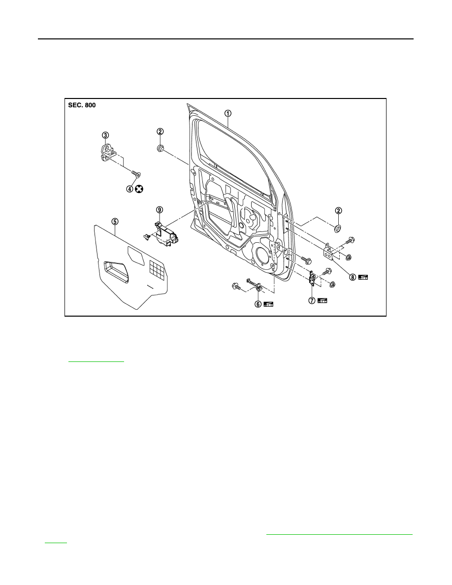
DOOR ASSEMBLY : Exploded View

INFOID:0000000009950609

DOOR ASSEMBLY : Removal and Installation

INFOID:0000000009950610

CAUTION:

• Perform work with 2 workers, because of its heavy weight.
• When removing and installing front door assembly, support door with a jack and shop cloth to pro-

tect door and body.

REMOVAL

1.

Remove mounting bolts of door check link on the vehicle.

2.

Remove front door harness grommet, and then pull out the harness from the vehicle.

3.

Disconnect front door harness connector.

4.

Remove door hinge mounting nuts (door side), and then remove door assembly.

INSTALLATION

Install in the reverse order of removal.

CAUTION:

• Check front door open/close, lock/unlock operation after installation.
• Check door hinge rotating part for poor lubrication. If necessary, apply body grease.
• After installation, perform the fitting adjustment. Refer to 

DLK-191, "DOOR ASSEMBLY : Adjust-

ment"

.

• After installation, apply touch-up paint (the body color) onto the head of door hinge mounting nuts.

1.

Front door panel

2.

Grommet

3.

Door striker

4.

TORX bolt

5.

Sealing screen

6.

Door check link

7.

Door hinge (lower)

8.

Door hinge (upper)

Refer to 

GI-4, "Components"

 for symbols in the figure.

JMKIA3956ZZ

FRONT DOOR

DLK-191

< REMOVAL AND INSTALLATION >

[WITH INTELLIGENT KEY SYSTEM]

C

D

E

F

G

H

I

J

L

M

A

B

DLK

N

O

P

DOOR ASSEMBLY : Adjustment

INFOID:0000000009950611

Check the clearance and surface height between front door and each part by visually and touching. 
If the clearance and the surface height are out of specification, adjust them according to the procedures
shown below.

1.

Front fender

2.

Front door 

3.

Rear door

4.

Body side outer

5.

Front door hinge (upper)

6.

Front door hinge (lower)

7.

Rear door hinge (upper)

8.

Rear door hinge (lower)

9.

Door striker

10.

TORX bolt

Refer to 

GI-4, "Components"

 for symbols in the figure.

JMKIA3837GB

DLK-192

< REMOVAL AND INSTALLATION >

[WITH INTELLIGENT KEY SYSTEM]

FRONT DOOR

Unit : mm (in)

1.

Remove front fender. Refer to  

DLK-188, "Removal and Installation"

.

2.

Loosen door hinge mounting nuts on door side.

3.

Adjust the surface height of front door according to the fitting standard dimension.

4.

Temporarily tighten door hinge mounting nuts on door side.

5.

Loosen door hinge mounting bolts on body side. 

6.

Raise front door at rear end to adjust clearance of the front door according to the fitting standard dimen-
sion.

7.

After adjustment tighten bolts and nuts to the specified torque.

8.

Install front fender. Refer to refer to 

DLK-188, "Removal and Installation"

.

DOOR STRIKER ADJUSTMENT

Adjust door striker so that it becomes parallel with door lock insertion direction.

DOOR STRIKER

DOOR STRIKER : Exploded View

INFOID:0000000009950612

DOOR STRIKER : Removal and Installation

INFOID:0000000009950613

REMOVAL

Portion

Clearance

Surface height

Front fender – Front door

A – A

3.5 – 5.5 (0.138 – 0.217)

- 1.0 – 1.0 (- 0.039 – 0.039)

Front door – Rear door

B – B

3.4 – 5.4 (0.134 – 0.213)

- 1.0 – 1.0 (- 0.039 – 0.039)

1.

Front door panel

2.

Grommet

3.

Door striker

4.

TORX bolt

5.

Sealing screen

6.

Door check link

7.

Door hinge (lower)

8.

Door hinge (upper)

Refer to 

GI-4, "Components"

 for symbols in the figure.

JMKIA3956ZZ

FRONT DOOR

DLK-193

< REMOVAL AND INSTALLATION >

[WITH INTELLIGENT KEY SYSTEM]

C

D

E

F

G

H

I

J

L

M

A

B

DLK

N

O

P

Remove TORX bolts, and then remove door striker.

INSTALLATION

Install in the reverse order of removal.

CAUTION:

• Check front door open/close, lock/unlock operation after installation.
• After installation, be sure to perform the fitting adjustment. Refer to 

DLK-191, "DOOR ASSEMBLY :

Adjustment"

.

DOOR HINGE

DOOR HINGE : Exploded View

INFOID:0000000009950614

DOOR HINGE : Removal and Installation

INFOID:0000000009950615

REMOVAL

CAUTION:

• Perform work with 2 workers, because of its heavy weight.
• When removing and installing front door assembly, support door with a jack and shop cloth to pro-

tect door and body.

1.

Remove front fender. Refer to 

DLK-188, "Removal and Installation"

.

2.

Remove front door assembly. Refer to 

DLK-190, "DOOR ASSEMBLY : Removal and Installation"

.

3.

Remove front door hinge mounting bolts (body side), and then remove front door hinge.

INSTALLATION

Install in the reverse order of removal.

CAUTION:

• Check front door open/close, lock/unlock operation after installation.

1.

Front door panel

2.

Grommet

3.

Door striker

4.

TORX bolt

5.

Sealing screen

6.

Door check link

7.

Door hinge (lower)

8.

Door hinge (upper)

Refer to 

GI-4, "Components"

 for symbols in the figure.

JMKIA3956ZZ


Content   ..  229  230  231  232   ..