Nissan Cube. Manual - part 230
DLK-186
< REMOVAL AND INSTALLATION >
[WITH INTELLIGENT KEY SYSTEM]
RADIATOR CORE SUPPORT
RADIATOR CORE SUPPORT
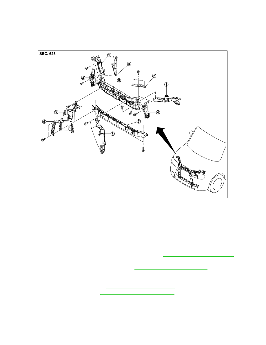
Exploded View
INFOID:0000000009950605
Removal and Installation
INFOID:0000000009950606
RADIATOR CORE SUPPORT UPPER
REMOVAL
1.
Remove front bumper fascia and bumper reinforcement. Refer to
EXT-12, "Removal and Installation"
2.
Remove hood lock. Refer to
DLK-210, "Removal and Installation"
3.
Remove front combination lamps (LH/RH). Refer to
EXL-191, "Removal and Installation"
.
4.
Remove air guide.
5.
Remove horn. Refer to
HRN-6, "Removal and Installation"
6.
Remove crash zone sensor. Refer to
SR-22, "Removal and Installation"
.
7.
Remove ambient sensor. Refer to
HAC-123, "Removal and Installation"
.
8.
Disconnect all harness from radiator core support upper.
9.
Remove air duct assembly. Refer to
EM-24, "Removal and Installation"
10. Remove radiator core support upper bracket (LH/RH).
11. Remove mounting bolts, and then remove radiator core support upper.
INSTALLATION
1.
Radiator core support side
2.
Radiator core support upper bracket
(LH)
3.
Radiator core support upper bracket
(RH)
4.
Radiator core reinforcement side
5.
Air guide
6.
Radiator core lower stay
7.
Radiator core support lower
8.
Radiator core support upper
JMKIA3625ZZ