Nissan Cube. Manual - part 144
CLUTCH FLUID
CL-9
< PERIODIC MAINTENANCE >
C
E
F
G
H
I
J
K
L
M
A
B
CL
N
O
P
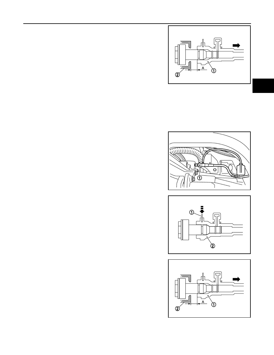
3.
Slide bleeding connector (1) in the direction of the arrow as
shown in the figure.
4.
Depress clutch pedal to gradually discharge clutch fluid.
CAUTION:
Since the inside of clutch tube is under hydraulic pressure,
hold the tube to prevent it from getting disconnected.
Refilling
INFOID:0000000009949666
CAUTION:
Keep painted surface on the body or other parts free of clutch fluid. If it spills, wipe up immediately
and wash the affected area with water.
1.
Check that there is no foreign material in reservoir tank and then fill with new clutch fluid.
CAUTION:
Never reuse drained clutch fluid.
2.
Connect a transparent vinyl hose to air bleeder of bleeding con-
nector (1).
3.
Press the lock pin (1) into the bleeding connector (2), and main-
tain the position.
4.
Slide bleeding connector (1) in the direction of the arrow as
shown in the figure.
5.
Slowly depress clutch pedal to the full stroke position and then
release the pedal.
CAUTION:
Since the inside of clutch tube is under hydraulic pressure,
hold the tube to prevent it from getting disconnected.
6.
Repeat step 5 at intervals of 2 or 3 seconds until new clutch fluid is discharged.
CAUTION:
Monitor clutch fluid level in reservoir tank so as not to empty the tank.
2
: Clutch housing
Dimension “A”
: 10 mm (0.39 in)
JPDIB0042ZZ
JPDIB0166ZZ
JPDIB0041ZZ
2
: Clutch housing
Dimension “A”
: 10 mm (0.39 in)
JPDIB0042ZZ