Nissan Cube. Manual - part 145
CLUTCH MASTER CYLINDER
CL-13
< REMOVAL AND INSTALLATION >
C
E
F
G
H
I
J
K
L
M
A
B
CL
N
O
P
CLUTCH MASTER CYLINDER
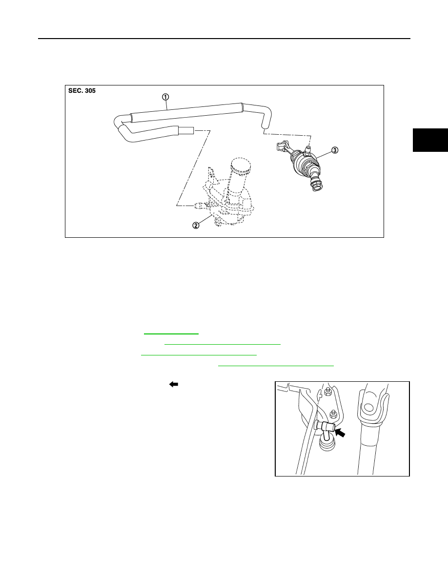
Exploded View
INFOID:0000000009949671
Removal and Installation
INFOID:0000000009949672
REMOVAL
CAUTION:
• Keep painted surface on the body or other parts free of clutch fluid. If it spills, wipe up immediately
and wash the affected area with water.
• Never disassemble master cylinder.
1.
Drain clutch fluid. Refer to
.
2.
Remove air duct (inlet). Refer to
EM-24, "Removal and Installation"
3.
Remove battery. Refer to
PG-82, "Removal and Installation"
4.
Remove air cleaner case and air ducts. Refer to
EM-24, "Removal and Installation"
.
5.
Remove hose from reservoir tank assembly and master cylinder.
6.
Remove master cylinder rod end (
) from clutch pedal.
1.
Hose
2.
Reservoir tank assembly
3.
Master cylinder
JPDIB0162ZZ
PCIB1491E