Nissan Versa Note. Manual - part 839


  Index      Nissan     Nissan Versa Note (2014 year) - Service and Repair Manual


Search            


Content   ..  837  838  839  840   ..


Nissan Versa Note. Manual - part 839


TM-236

< REMOVAL AND INSTALLATION >

[CVT: RE0F11A]

KEY INTERLOCK CABLE

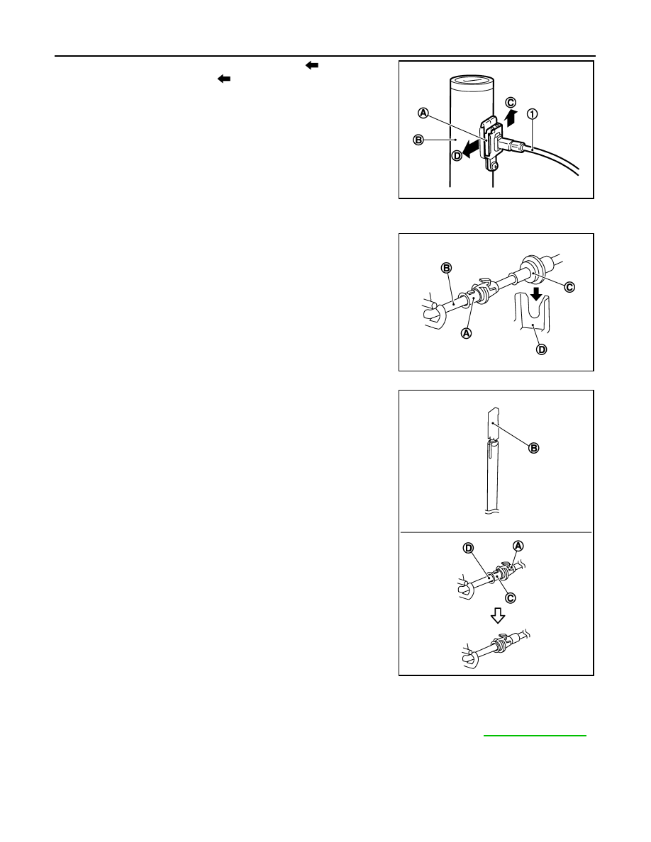
9. Lift lock plate (A) in the direction of the arrow (

C) and remove

in the direction of the arrow (

D).

10. Remove the key interlock cable from the key cylinder.
11. Disengage the clips and remove the key interlock cable from the

vehicle.

INSTALLATION

Installation is in the reverse order of removal.

• Temporarily install the adjust holder (A) to the key interlock rod (B).

• Install the casing cap (C) to the cable bracket (D) on the shift

selector assembly.

CAUTION:

• Do not bend or twist key interlock cable excessively when

installing.

• After installing key interlock cable to cable bracket (D) on

shift selector assembly, make sure casing caps (C) is firmly

secured in cable bracket (D) on shift selector assembly.

• If casing cap (C) is loose [less than 39.2 N (4.0 kg, 8.8 lb)

removing force], replace key interlock cable.

• Slide the slider (A) toward the key interlock rod (D) while pressing

the pull lock (B) down to securely connect the adjust holder (C)

with the key interlock rod (D).

CAUTION:

• Do not press tabs when holding slider (A).

• Do not apply any side to side force to key interlock rod (D)

when sliding slider (A).

Inspection

INFOID:0000000009019776

INSPECTION AFTER INSTALLATION

• Check the CVT operation. If a malfunction is found, adjust the CVT position. Refer to 

TM-230, "Inspection"

.

• Make sure the key can be removed only when the shift selector is in the “P” position.

• Make sure the ignition switch will not turn to LOCK position when the shift selector is not in the “P” position.

(1)

:Key interlock cable

(B)

:Key cylinder

JSDIA1798ZZ

JSDIA1799ZZ

JSDIA1800ZZ

TCM

TM-237

< REMOVAL AND INSTALLATION >

[CVT: RE0F11A]

C

E

F

G

H

I

J

K

L

M

A

B

TM

N

O

P

TCM

Exploded View

INFOID:0000000009019777

Removal and Installation

INFOID:0000000009019778

CAUTION:

When replacing TCM, note the “CVTF DETERIORATION DATE” value displayed on CONSULT “CON-

FORM CVTF DETERIORTN” in MAINTENANCE BOOKLET, before starting the operation.

NOTE:

When replacing the TCM and transaxle assembly as a set, replace the transaxle assembly first and then

replace the TCM. Refer to 

TM-127, "Description"

.

REMOVAL

1. Remove the battery. Refer to 

PG-67, "Removal and Installation (Battery)"

.

2. Disconnect the harness connector from the TCM.
3. Remove the TCM and bracket as an assembly.
4. Remove the TCM from the bracket (if necessary).

INSTALLATION

Installation is in the reverse order of removal.

Adjustment

INFOID:0000000009019779

ADJUSTMENT AFTER INSTALLATION

Perform "ADDITIONAL SERVICE WHEN REPLACING TCM". Refer to 

TM-127, "Description"

.

1.

TCM

2.

Bracket

3.

Clip

Front

AWBIA1482ZZ

TM-238

< REMOVAL AND INSTALLATION >

[CVT: RE0F11A]

AIR BREATHER HOSE

AIR BREATHER HOSE

Removal and Installation

INFOID:0000000009019780

REMOVAL

1. Remove air duct (inlet). Refer to 

EM-26, "Exploded View"

.

2. Remove air breather hose from transaxle assembly.

INSTALLATION

Installation is in the reverse order of removal.

CAUTION:

• Check that air breather hose is not collapsed or blocked due to folding or bending when installed.

• Be sure to insert air breather hose (1) fully until it reaches the

base of the transaxle tube (A).

JSDIA1978ZZ

G SENSOR

TM-239

< REMOVAL AND INSTALLATION >

[CVT: RE0F11A]

C

E

F

G

H

I

J

K

L

M

A

B

TM

N

O

P

G SENSOR

Exploded View

INFOID:0000000009019781

Removal and Installation

INFOID:0000000009019782

CAUTION:

• Do not drop or strike G sensor, because it may be damaged by impact.

• Do not use a power tool.

REMOVAL

1. Disconnect the battery negative terminal. Refer to 

PG-67, "Exploded View"

.

2. Remove center console assembly. Refer to 

IP-18, "Removal and Installation"

.

3. Disconnect the harness connector from G sensor.
4. Remove G sensor.

INSTALLATION

Installation is in the reverse order of removal.

Adjustment

INFOID:0000000009019783

ADJUSTMENT AFTER INSTALLATION

Perform “G SENSOR CALIBRATION”. Refer to 

TM-130, "Description"

.

1.

G sensor

Front

JSDIA1922GB


Content   ..  837  838  839  840   ..