Nissan Versa Note. Manual - part 838
TM-232
< REMOVAL AND INSTALLATION >
[CVT: RE0F11A]
CONTROL CABLE
CONTROL CABLE
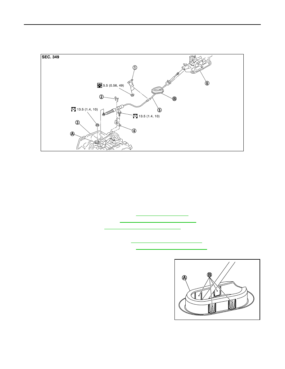
Exploded View
INFOID:0000000009019771
Removal and Installation
INFOID:0000000009019772
CAUTION:
Always apply the parking brake before performing removal and installation.
REMOVAL
1. Remove the battery negative terminal. Refer to
2. Remove the TCM and bracket. Refer to
TM-237, "Removal and Installation"
.
3. Remove the IPDM E/R. Refer to
PCS-31, "Removal and Installation"
.
4. Remove the battery tray and bracket.
5. Remove instrument lower panel LH. Refer to
IP-24, "Removal and Installation"
.
6. Remove the center console assembly. Refer to
IP-18, "Removal and Installation"
7. Remove the control cable from the shift selector assembly.
8. Disengage the pawls (B) of the grommet (A), and pull downward
to remove.
9. Remove the control cable nut from the manual lever.
1.
Bracket B
2.
Lock plate
3.
Transaxle assembly
4.
Bracket A
5.
Control cable
6.
CVT shift selector assembly
A: Manual lever
B: Grommet
JSDIA1921GB
JSDIA1809ZZ