Nissan Versa Note. Manual - part 789


  Index      Nissan     Nissan Versa Note (2014 year) - Service and Repair Manual


Search            


Content   ..  787  788  789  790   ..


Nissan Versa Note. Manual - part 789


TM-36

< UNIT DISASSEMBLY AND ASSEMBLY >

[5MT: RS5F91R]

TRANSAXLE ASSEMBLY

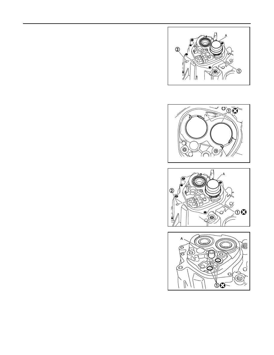
42. Expand snap rings (1) and remove input shaft rear bearing and

mainshaft rear bearing from transaxle case, using Tool (A).

43. Remove snap rings from transaxle case.
44. Remove check balls (2) from transaxle case.

Assembly

INFOID:0000000009417476

1. Install snap rings (1) along transaxle case groove so that notch

mates with housing as shown.

CAUTION:

• Do not reuse snap rings.

• Check snap ring installation direction.

• Be sure to align notch with housing.

2. Expand snap rings (1) and install input shaft rear bearing and

mainshaft rear bearing to transaxle case, using Tool (A).

CAUTION:

Check that snap ring is correctly installed within bearing

groove.

3. Install check balls (2) to transaxle case.

4. Install bushings (1) until they reach transaxle case, using suit-

able tool (A).

CAUTION:

Do not reuse bushings.

5. Apply gear oil to O-ring, and then install it to control shaft.

CAUTION:

Do not reuse O-ring.

Tool number

: ST35300000 ( — )

PCIB1535E

PCIB1547E

Tool number

: ST35300000 ( — )

PCIB1548E

JPDIC0636ZZ

TRANSAXLE ASSEMBLY

TM-37

< UNIT DISASSEMBLY AND ASSEMBLY >

[5MT: RS5F91R]

C

E

F

G

H

I

J

K

L

M

A

B

TM

N

O

P

6. Install control shaft (1) to transaxle case, and tighten bolts (

)

to the specified torque.

CAUTION:

Replace control shaft and selector as a set.

7. Install selector to control shaft, and then install retaining pin (

)

to selector, using suitable tool.

CAUTION:

• Be careful with the orientation of selector.

• Replace control shaft and selector as a set.

• Do not reuse retaining pin.

8. Install gear catch, spring, and bushing to transaxle case, and

then tighten bolt (

) to the specified torque.

CAUTION:

Replace gear catch, spring, and bushing as a set.

9. Install oil gutter to transaxle case.

10. Install air breather inner tube (2) to transaxle case.

CAUTION:

Do not damage air breather inner tube.

NOTE:

It is easier to install when air breather inner tube end is wrapped

and narrowed by tape. Remove tape after installation.

11. Insert 2-way connector (1) straight, and then install it to air

breather inner tube.

CAUTION:

Check air breather inner tube for twists after installing.

12. Install differential side oil seals (1) to clutch housing and tran-

saxle case, using Tool.

PCIB1540E

SCIA1726J

JPDIC0533ZZ

PCIB1541E

(B)

: Transaxle case side

(C)

: Clutch housing side

Dimension (L

1

)

: 5.7 – 6.3 mm (0.224 – 0.248 in)

Dimension (L

2)

: 2.4 – 3.0 mm (0.094 – 0.118 in)

Tool number

: KV32500QAA ( — )

JPDIC0401ZZ

TM-38

< UNIT DISASSEMBLY AND ASSEMBLY >

[5MT: RS5F91R]

TRANSAXLE ASSEMBLY

CAUTION:

• Do not reuse differential side oil seal.

• Do not tilt differential side oil seal.

• Do not damage clutch housing and transaxle case.

13. Install differential side bearing outer races until they reach clutch

housing and transaxle case, using Tool (A).

CAUTION:

Replace differential side bearing outer race and differential

side bearing as a set.

14. Install bushings (1) until they reach clutch housing, using suit-

able tool (A).

CAUTION:

Do not reuse bushings.

15. Install oil channel to clutch housing.

CAUTION:

Do not reuse oil channel.

16. Install mainshaft front bearing so that it becomes even with

clutch housing surface, using Tool (A).

17. Install input shaft front bearing so that it becomes even with

clutch housing surface, using Tool (A).

18. Install pinion gear, pinion shaft, and plug to clutch housing.

Tool number

: KV32300QAE ( — )

PCIB1549E

JPDIC0637ZZ

Tool number : ST33400001 ( — )

PCIB1544E

Tool number

: KV40100900 ( — )

PCIB1545E

TRANSAXLE ASSEMBLY

TM-39

< UNIT DISASSEMBLY AND ASSEMBLY >

[5MT: RS5F91R]

C

E

F

G

H

I

J

K

L

M

A

B

TM

N

O

P

19. Install final drive (1) to clutch housing.
20. Install dowel pins (2) and magnet to clutch housing.

CAUTION:

Do not reuse dowel pins.

21. Install reverse gear to clutch housing, and then install retaining

pin to clutch housing, using suitable tool.

CAUTION:

Do not reuse retaining pin.

22. Install 1st-2nd shift fork to 1st-2nd fork rod, and then install

retaining pin to 1st-2nd shift fork.

CAUTION:

• Do not reuse retaining pin.

• Replace 1st-2nd fork rod and 1st-2nd shift fork as a set.

23. Set 1st-2nd fork rod assembly (1) onto mainshaft assembly (2),

and then install them to clutch housing.

24. Install lock pins (

) to clutch housing.

25. Install 3rd-4th shift fork to 3rd-4th fork rod, and then install

retaining pin to 3rd-4th shift fork.

CAUTION:

• Do not reuse retaining pin.

• Replace 3rd-4th fork rod and 3rd-4th shift fork as a set.

26. Install 3rd-4th fork rod assembly (1), 3rd-4th coupling sleeve (2),

and input shaft assembly (3) to clutch housing.

a. Pull 1st-2nd fork rod (4) up, and then maintain the neutral posi-

tion.

b. Set 3rd-4th fork rod assembly onto 3rd-4th coupling sleeve, and

then install them together with input shaft assembly to clutch

housing.

CAUTION:

• Set lock pin (3rd-4th fork rod side) onto 1st-2nd fork rod

groove and then install 3rd-4th fork rod assembly.

PCIB1533E

MCIB0033E

PCIB1532E

JPDIC0534ZZ

PCIB1628E


Content   ..  787  788  789  790   ..