Nissan Versa Note. Manual - part 700


  Index      Nissan     Nissan Versa Note (2014 year) - Service and Repair Manual


Search            


Content   ..  698  699  700  701   ..


Nissan Versa Note. Manual - part 700


B2556 PUSH-BUTTON IGNITION SWITCH

SEC-79

< DTC/CIRCUIT DIAGNOSIS >

[WITH INTELLIGENT KEY SYSTEM]

C

D

E

F

G

H

I

J

L

M

A

B

SEC

N

O

P

B2556 PUSH-BUTTON IGNITION SWITCH

DTC Logic

INFOID:0000000009705880

DTC DETECTION LOGIC

DTC CONFIRMATION PROCEDURE

1.

PERFORM DTC CONFIRMATION PROCEDURE

1. Press push-button ignition switch under the following condition.

-

Brake pedal: Not depressed

2. Release push-button ignition switch and wait 100 seconds or more.

3. Check DTC in Self Diagnostic Result mode of BCM using CONSULT.
Is DTC detected?

YES

>> Go to 

SEC-79, "Diagnosis Procedure"

.

NO

>> Inspection End.

Diagnosis Procedure

INFOID:0000000009705881

Regarding Wiring Diagram information, refer to 

SEC-40, "Wiring Diagram"

.

1.

CHECK PUSH-BUTTON IGNITION SWITCH INPUT SIGNAL

1. Turn ignition switch OFF.

2. Disconnect push-button ignition switch connector.

3. Check voltage between push-button ignition switch harness connector and ground.

Is the inspection result normal?

YES

>> GO TO 4.

NO

>> GO TO 2.

2.

CHECK PUSH-BUTTON IGNITION SWITCH CIRCUIT

1. Disconnect BCM connector and IPDM E/R connector.

2. Check continuity between push-button ignition switch harness connector and BCM harness connector.

3. Check continuity between push-button ignition switch harness connector and ground.
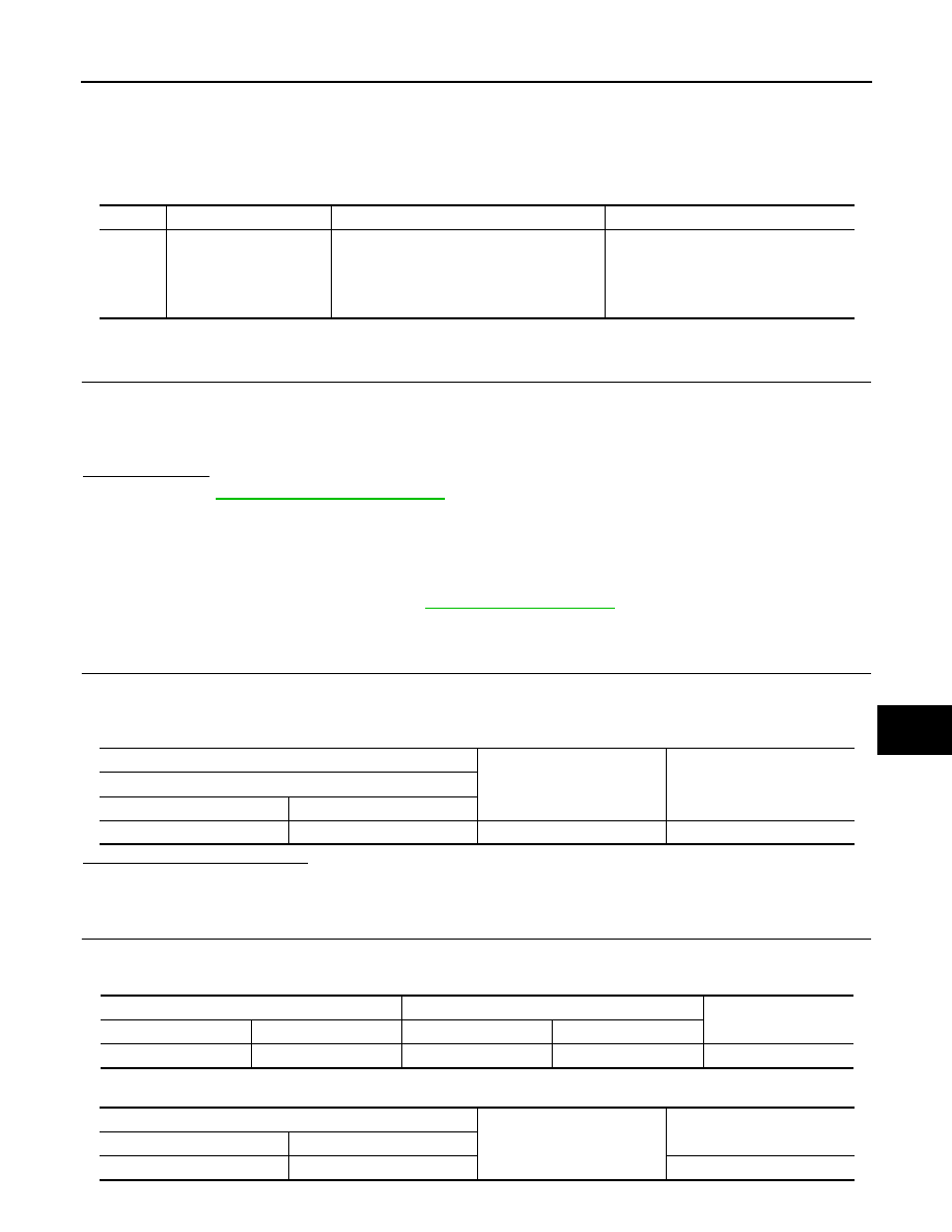
DTC No.

Trouble diagnosis name

DTC detecting condition

Possible cause

B2556

ENG START SW

BCM detects the push-button ignition switch 
stuck at ON for 100 seconds or more.

• Harness or connectors

(Push-button ignition switch circuit is 
shorted.)

• Push-button ignition switch
• BCM

(+)

(–)

Voltage (V)

(Approx.)

Push-button ignition switch

Connector

Terminal

M25

8

Ground

12

Push-button ignition switch

BCM

Continuity

Connector

Terminal

Connector

Terminal

M25

8

M98

76

Yes

Push-button ignition switch

Ground

Continuity

Connector

Terminal

M25

8

No

SEC-80

< DTC/CIRCUIT DIAGNOSIS >

[WITH INTELLIGENT KEY SYSTEM]

B2556 PUSH-BUTTON IGNITION SWITCH

Is the inspection result normal?

YES

>> GO TO 3.

NO

>> Repair or replace harness.

3.

REPLACE BCM

1. Replace BCM. Refer to 

BCS-70, "Removal and Installation"

.

2. Perform initialization of BCM and registration of all Intelligent Keys using CONSULT. Refer to the CON-

SULT Immobilizer mode and follow the on-screen instructions.

>> Inspection End.

4.

CHECK PUSH-BUTTON IGNITION SWITCH GROUND CIRCUIT

Check continuity between push-button ignition switch harness connector and ground.

Is the inspection result normal?

YES

>> GO TO 5.

NO

>> Repair or replace harness.

5.

CHECK PUSH-BUTTON IGNITION SWITCH

Refer to 

SEC-80, "Component Inspection"

.

Is the inspection result normal?

YES

>> GO TO 6.

NO

>> Replace push-button ignition switch. Refer to 

SEC-127, "Removal and Installation"

.

6.

CHECK INTERMITTENT INCIDENT

Refer to 

GI-41, "Intermittent Incident"

.

>> Inspection End.

Component Inspection

INFOID:0000000009705882

1.

CHECK PUSH-BUTTON IGNITION SWITCH

1. Turn ignition switch OFF.

2. Disconnect push-button ignition switch connector.

3. Check continuity between push-button ignition switch terminals.

Is the inspection result normal?

YES

>> Inspection End.

NO

>> Replace push-button ignition switch. Refer to 

SEC-127, "Removal and Installation"

.

Push-button ignition switch

Ground

Continuity

Connector

Terminal

M25

4

Yes

Push-button ignition switch

Condition

Continuity

Terminal

4

8

Push-button ignition 
switch

Pressed

Yes

Not pressed

No

B2557 VEHICLE SPEED

SEC-81

< DTC/CIRCUIT DIAGNOSIS >

[WITH INTELLIGENT KEY SYSTEM]

C

D

E

F

G

H

I

J

L

M

A

B

SEC

N

O

P

B2557 VEHICLE SPEED

DTC Logic

INFOID:0000000009705883

DTC DETECTION LOGIC

NOTE:

• If DTC B2557 is displayed with DTC U1000, first perform the trouble diagnosis for DTC U1000. Refer to

BCS-60, "DTC Logic"

.

• If DTC B2557 is displayed with DTC U1010, first perform the trouble diagnosis for DTC U1010. Refer to

BCS-61, "DTC Logic"

.

DTC CONFIRMATION PROCEDURE

1.

PERFORM DTC CONFIRMATION PROCEDURE

1. Start engine and wait 10 seconds or more.

2. Drive the vehicle at a vehicle speed of 10 km/h (6.2 MPH) or more for 10 seconds or more.

3. Check DTC in Self Diagnostic Result mode of BCM using CONSULT.
Is DTC detected?

YES

>> Go to 

SEC-81, "Diagnosis Procedure"

.

NO

>> Inspection End.

Diagnosis Procedure

INFOID:0000000009705884

1.

CHECK DTC OF “ABS ACTUATOR AND ELECTRIC UNIT (CONTROL UNIT)”

Check DTC in Self Diagnostic Result mode of ABS using CONSULT.
Is DTC detected?

YES

>> Perform the trouble diagnosis related to the detected DTC. Refer to 

BRC-41, "DTC Index"

.

NO

>> GO TO 2.

2.

CHECK DTC OF COMBINATION METER

Check DTC in Self Diagnostic Result mode of METER/M&A using CONSULT.
Is DTC detected?

YES

>> Perform the trouble diagnosis related to the detected DTC. Refer to 

MWI-21, "DTC Index"

.

NO

>> GO TO 3.

3.

CHECK INTERMITTENT INCIDENT

Refer to 

GI-41, "Intermittent Incident"

.

>> Inspection End.

DTC No.

Trouble diagnosis name

DTC detecting condition

Possible causes

B2557

VEHICLE SPEED

BCM detects one of the following conditions for 10 
seconds continuously.
• Vehicle speed signal from “combination meter” 

is 10 km/h (6.2 MPH) or more and vehicle 
speed signal from “ABS actuator and electric 
unit (control unit)” is 4 km/h (2.5 MPH) or less

• Vehicle speed signal from “combination meter” 

is 4 km/h (2.5 MPH) or less and vehicle speed 
signal from “ABS actuator and electric unit 
(control unit)” is 10 km/h (6.2 MPH) or more

• Harness or connectors

(The CAN communication line is 
open or shorted.)

• Combination meter
• ABS actuator and electric unit 

(control unit)

SEC-82

< DTC/CIRCUIT DIAGNOSIS >

[WITH INTELLIGENT KEY SYSTEM]

B2601 SHIFT POSITION

B2601 SHIFT POSITION

DTC Logic

INFOID:0000000009705885

DTC DETECTION LOGIC

NOTE:

• If DTC B2601 is displayed with DTC U1000, first perform the trouble diagnosis for DTC U1000. Refer to

BCS-60, "DTC Logic"

.

• If DTC B2601 is displayed with DTC U1010, first perform the trouble diagnosis for DTC U1010. Refer to

BCS-61, "DTC Logic"

.

DTC CONFIRMATION PROCEDURE

1.

PERFORM DTC CONFIRMATION PROCEDURE

1. Shift the selector lever to the P position.

2. Turn ignition switch ON and wait 2 seconds or more.

3. Shift the selector lever to any position other than P and wait 2 seconds or more.

4. Check DTC in Self Diagnostic Result mode of BCM using CONSULT.
Is DTC detected?

YES

>> Go to 

SEC-82, "Diagnosis Procedure"

.

NO

>> Inspection End.

Diagnosis Procedure

INFOID:0000000009705886

Regarding Wiring Diagram information, refer to 

SEC-40, "Wiring Diagram"

.

1.

CHECK CVT SHIFT SELECTOR CIRCUIT (BCM)

1. Turn ignition switch OFF.

2. Disconnect CVT shift selector (park position switch) connector.

3. Disconnect BCM connector.

4. Check continuity between CVT shift selector (park position switch) harness connector and BCM harness

connector.

5. Check continuity between CVT shift selector (park position switch) harness connector and ground.

Is the inspection result normal?

YES

>> GO TO 2.

NO

>> Repair or replace harness.

DTC No.

Trouble diagnosis name

DTC detecting condition

Possible cause

B2601

SHIFT P SIGNAL

When there is a difference between P range 
signal from CVT shift selector (park position 
switch) and P position signal from IPDM E/R 
(CAN).

• Harness or connectors

(CAN communication line is open or 
shorted.)

• Harness or connectors

[CVT shift selector (park position 
switch) circuit is open or shorted.]

• IPDM E/R
• BCM

CVT shift selector (park position switch)

BCM

Continuity

Connector

Terminal

Connector

Terminal

M38

8

M97

37

Yes

CVT shift selector (park position switch)

Ground

Continuity

Connector

Terminal

M38

8

No


Content   ..  698  699  700  701   ..