Nissan Versa Note. Manual - part 374


  Index      Nissan     Nissan Versa Note (2014 year) - Service and Repair Manual


Search            


Content   ..  372  373  374  375   ..


Nissan Versa Note. Manual - part 374


EM-12

< BASIC INSPECTION >

[HR16DE]

CAMSHAFT VALVE CLEARANCE

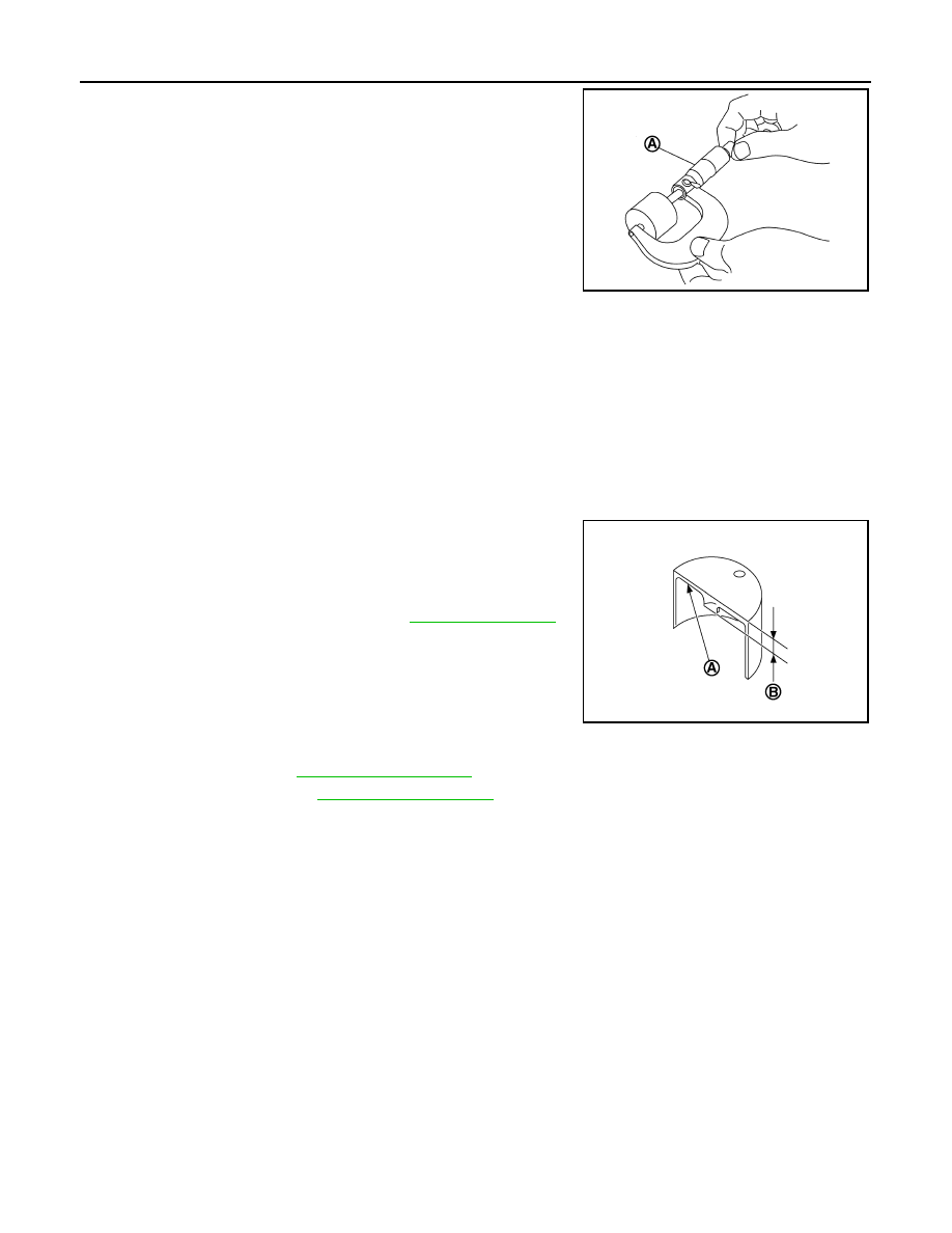
3. Measure the center thickness of the removed valve lifters using

a suitable tool (A).

4. Use the equation below to calculate valve lifter thickness for replacement.

• Crown surface thickness of new valve lifter (B) can be identi-

fied by stamp mark (A) on the under side of the lifter.

NOTE:

Available thickness of valve lifter: 26 sizes range 3.00 to 3.50

mm (0.1181 to 0.1378 in) in increments of 0.02 mm (0.0008 in)

when manufactured at factory. Refer to 

EM-116, "Camshaft"

.

• Stamp mark “302” indicates 3.02 mm (0.1189 in) in thickness.

5. Install the correct thickness valve lifter.
6. Install camshaft. Refer to 

EM-60, "Exploded View"

.

7. Install timing chain. Refer to 

EM-51, "Exploded View"

.

8. Manually rotate crankshaft pulley a few rotations. 
9. Check that valve clearances are within specification. Refer to “INSPECTION”.
10. Installation of remaining components is in the reverse order of removal.
11. Warm up the engine, and check for unusual noise and vibration.

PBIC3195J

Valve lifter thickness calculation:

t = t

1

 + (C

– C

2

)

t

= Valve lifter thickness to be replaced

t

1

= Removed valve lifter thickness

C

1

= Measured valve clearance

C

2

= Standard valve clearance at 20

°C (68°F):

Intake

: 0.30 mm (0.012 in)

Exhaust

: 0.33 mm (0.013 in)

PBIC3196J

COMPRESSION PRESSURE

EM-13

< BASIC INSPECTION >

[HR16DE]

C

D

E

F

G

H

I

J

K

L

M

A

EM

N

P

O

COMPRESSION PRESSURE

Inspection

INFOID:0000000009444710

1. Warm up engine to full operating temperature and then turn it off. 
2. Release fuel pressure. Refer to 

EC-135, "Work Procedure"

3. Remove ignition coil and spark plug from each cylinder. Refer to 

EM-48, "Exploded View"

.

4. Connect engine tachometer (not required in use of CONSULT).
5. Install compression gauge (B) with an adapter (A) into spark

plug hole.

• Use an adapter with a diameter (a) smaller than 20 mm (0.79

in). Otherwise, it may be caught by cylinder head during

removal.

6. With accelerator pedal fully depressed, turn ignition switch to »»» for cranking. When the gauge pointer

stabilizes, read the compression pressure and the engine rpm. Perform these steps to check each cylin-

der.

CAUTION:

Always use a fully charged battery to obtain the specified engine speed.

• If the engine speed is out of the specified range, check the battery. Check the engine speed again with a

fully charged battery. 

• If some cylinders have low compression pressure, pour a small amount of engine oil into the spark plug

hole to recheck the compression.

- If the added engine oil improves the compression, the piston rings may be worn or damaged. Check the

piston rings and replace if necessary.

- If the compression pressure remains low despite the addition of engine oil, the valves may be malfunc-

tioning. Check the valves for damage. Replace the valve or valve seat as necessary.

• If two adjacent cylinders have respectively low compression pressure and their compression remains

low even after the addition of engine oil the head gasket may be leaking, or valves in adjacent cylinders

may be damaged. Inspect and repair as required.

• If the compression pressure is below the minimum value, check the valve clearances and parts associ-

ated with the combustion chamber (valve, valve seat, piston, piston ring, cylinder bore, cylinder head,

cylinder head gasket). After repairing, measure the compression pressure again.

7. After inspection is completed, install removed parts.
8. Start the engine, and ensure that the engine runs smoothly.
9. Perform trouble diagnosis. If DTC appears, erase it. Refer to 

EC-118, "Work Flow"

.

JPBIA4119ZZ

(a)

: Less than 20 mm (0.79 in)

JPBIA0171ZZ

Compression pressure : Refer to 

EM-115, "General Specification"

.

EM-14

< SYMPTOM DIAGNOSIS >

[HR16DE]

NOISE, VIBRATION AND HARSHNESS (NVH) TROUBLESHOOTING

SYMPTOM DIAGNOSIS

NOISE, VIBRATION AND HARSHNESS (NVH) TROUBLESHOOTING

NVH troubleshooting Chart

INFOID:0000000009444711

1. Locate the area where noise occurs.
2. Confirm the type of noise.
3. Specify the operating condition of engine.

JPBIA4739GB

NOISE, VIBRATION AND HARSHNESS (NVH) TROUBLESHOOTING

EM-15

< SYMPTOM DIAGNOSIS >

[HR16DE]

C

D

E

F

G

H

I

J

K

L

M

A

EM

N

P

O

4. Check specified noise source.
If necessary, repair or replace these parts.

A: Closely related B: Related C: Sometimes related —: Not related

Location 

of noise

Type of 

noise

Operating condition of engine

Source of 

noise

Check item

Refer-

ence page

Before 

warm-

up

After 

warm-

up

When 

start-

ing

When 

idling

When 

racing

While 

driving

Top of en-
gine rock-
er cover
cylinder 
head

Ticking or 
clicking

C

A

A

B

Tappet 
noise

Valve clearance

EM-10

Rattle

C

A

A

B

C

Camshaft 
bearing 
noise

Camshaft journal oil 
clearance
Camshaft runout

EM-116

Crank-
shaft pul-
ley
cylinder 
block (side 
of engine)
oil pan

Slap or 
knock

A

B

B

Piston pin 
noise

Piston to piston pin oil 
clearance
Connecting rod bushing 
oil clearance

EM-120

Slap or 
rap

A

B

B

A

Piston 
slap noise

Piston to cylinder bore 
clearance
Piston ring side clear-
ance
Piston ring end gap
Connecting rod bend 
and torsion

EM-120

Knock

A

B

C

B

B

B

Connect-
ing rod 
bearing 
noise

Connecting rod bushing 
oil clearance 
Connecting rod bearing 
oil clearance

EM-120
EM-124

Knock

A

B

A

B

C

Main bear-
ing noise

Main bearing oil clear-
ance
Crankshaft runout

EM-123
EM-120

Front of 
engine
front cover

Tapping or 
ticking

A

A

B

B

B

Timing 
chain and 
chain ten-
sioner 
noise

Timing chain cracks 
and wear
Timing chain tensioner 
operation

EM-51
EM-51

Front of 
engine

Squeak-
ing or fizz-
ing

A

B

B

C

Drive belt 
(Sticking 
or slip-
ping)

Drive belt deflection

EM-115

Creaking

A

B

A

B

A

B

Drive belt 
(Slipping)

Idler pulley bearing op-
eration

Squall
Creak

A

B

B

A

B

Water 
pump 
noise

Water pump operation

CO-19


Content   ..  372  373  374  375   ..