Nissan Versa Note. Manual - part 375
EM-16
< PERIODIC MAINTENANCE >
[HR16DE]
DRIVE BELT
PERIODIC MAINTENANCE
DRIVE BELT
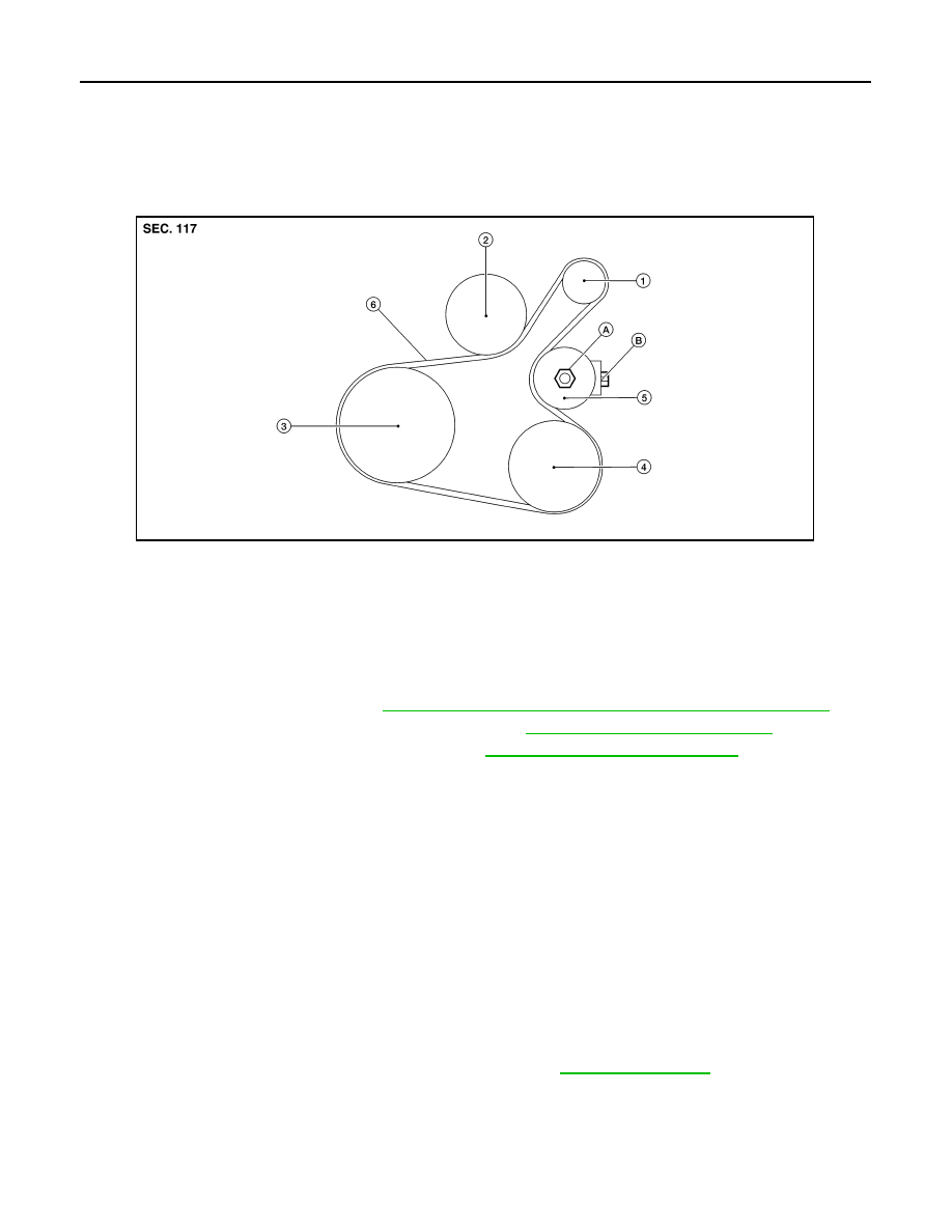
Exploded View
INFOID:0000000009444712
Removal and Installation
INFOID:0000000009444713
REMOVAL
1. Remove engine undercover. Refer to
EXT-37, "FRONT UNDER COVER : Removal and Installation"
.
2. Remove wheel and tire (RH) using a power tool. Refer to
WT-45, "Removal and Installation"
3. Partially remove the fender protector (RH). Refer to
EXT-36, "Removal and Installation"
.
4. Loosen the lock nut and then release the belt tension by turning the adjusting bolt.
5. Remove the drive belt.
INSTALLATION
1. Pull the idler pulley in the loosening direction, and then temporarily tighten the lock nut to the following
torque.
NOTE:
Do not move the lock nut from the temporary tightened position. Go to step 2.
2. Install the drive belt on each pulley.
CAUTION:
• Check that there is no engine oil, grease, or engine coolant, etc. in pulley grooves.
• Check that the belt seats securely inside the groove on each pulley.
3. Adjust drive belt tension by turning the adjusting bolt. Refer to
CAUTION:
• Perform the belt tension adjustment with the lock nut temporarily tightened to the torque specifi-
cation listed in step 1 which prevents the idler pulley from tilting.
• When checking immediately after installation, first adjust it to the specified value. Then, after
turning crankshaft two turns or more, readjust to the specified value to avoid variation in deflec-
tion between pulleys.
1.
Generator
2.
Water pump
3.
Crankshaft pulley
4.
A/C compressor (with A/C models)
Idler pulley (without A/C models)
5.
Tensioner idler pulley
6.
Drive belt
ALBIA1157ZZ
Lock nut
(Temporary tightening)
: 4.4 N·m (0.45 kg-m, 39 in-lb)