Nissan Rogue. Manual - part 796


  Index      Nissan     Nissan Rogue (2015 year) - Service and Repair Manual


Search            


Content   ..  794  795  796  797   ..


Nissan Rogue. Manual - part 796


SYSTEM

INL-11

< SYSTEM DESCRIPTION >

C

D

E

F

G

H

I

J

K

M

A

B

INL

N

O

P

AUTO LIGHT ADJUSTMENT SYSTEM : System Description

INFOID:0000000011279199
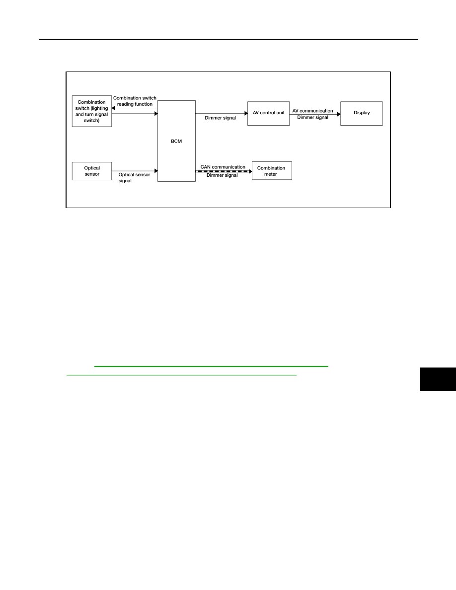
SYSTEM DIAGRAM

OUTLINE

 Auto light adjustment system is controlled by each function of BCM, combination meter and AV control unit

Controlled by BCM:

• Auto light system

• Auto light adjustment system

AUTO LIGHT ADJUSTMENT SYSTEM

Description

• BCM supplies voltage to the optical sensor when the ignition switch is turned ON.

• Optical sensor converts outside brightness (lux) to voltage and transmits the optical sensor signal to BCM.

• BCM judges dimming/brightening of combination meter and display according to brightness outside the vehi-

cle, when ignition switch is ON.

• BCM transmits dimmer signal to combination meter via CAN communication, according to auto light adjust-

ment conditions. Dimmer signal is also transmitted to AV control unit.

NOTE:

As to dimming/brightening timing, the sensitivity depends on settings. The settings can be changed with CON-

SULT. Refer to 

BCS-19, "HEADLAMP : CONSULT Function (BCM - HEADLAMP)"

 (with Intelligent Key sys-

tem) or 

BCS-90, "HEADLAMP : CONSULT Function (BCM - HEADLAMP)"

 (without Intelligent Key system).

ALLIA1621GB

INL-12

< SYSTEM DESCRIPTION >

DIAGNOSIS SYSTEM (BCM) (WITH INTELLIGENT KEY SYSTEM)

DIAGNOSIS SYSTEM (BCM) (WITH INTELLIGENT KEY SYSTEM)

COMMON ITEM
COMMON ITEM : CONSULT Function (BCM - COMMON ITEM)

INFOID:0000000011403305

APPLICATION ITEM

CONSULT performs the following functions via CAN communication with BCM.

SYSTEM APPLICATION

BCM can perform the following functions.

INT LAMP

Direct Diagnostic Mode

Description

Ecu Identification

The BCM part number is displayed.

Self Diagnostic Result

The BCM self diagnostic results are displayed.

Data Monitor

The BCM input/output data is displayed in real time.

Active Test

The BCM activates outputs to test components.

Work support

The settings for BCM functions can be changed.

Configuration

• The vehicle specification can be read and saved.
• The vehicle specification can be written when replacing BCM.

CAN Diag Support Mntr

The result of transmit/receive diagnosis of CAN communication is displayed.

System

Sub System

Direct Diagnostic Mode

E

cu

 Id

en

tifi

ca

tio

n

Se

lf Di

ag

no

st

ic Re

su

lt

Da

ta

 Mo

ni

tor

A

cti

ve

 T

est

W

o

rk support

Co

nf

igu

rat

ion

CA

N Diag

 Su

pp

ort Mn

tr

Door lock

DOOR LOCK

×

×

×

×

Rear window defogger

REAR DEFOGGER

×

×

×

Warning chime

BUZZER

×

×

Interior room lamp timer

INT LAMP

×

×

×

Exterior lamp

HEADLAMP

×

×

×

Wiper and washer

WIPER

×

×

×

Turn signal and hazard warning lamps FLASHER

×

×

Intelligent Key system

INTELLIGENT KEY

×

×

×

×

Combination switch

COMB SW

×

BCM

BCM

×

×

×

×

×

Immobilizer

IMMU

×

×

×

Interior room lamp battery saver

BATTERY SAVER

×

×

Back door open

TRUNK

×

Vehicle security system

THEFT ALM

×

×

×

RAP system

RETAINED PWR

×

Signal buffer system

SIGNAL BUFFER

×

Air conditioner 

AIR CONDITIONER 

×

DIAGNOSIS SYSTEM (BCM) (WITH INTELLIGENT KEY SYSTEM)

INL-13

< SYSTEM DESCRIPTION >

C

D

E

F

G

H

I

J

K

M

A

B

INL

N

O

P

INT LAMP : CONSULT Function (BCM - INT LAMP)

INFOID:0000000011403306

DATA MONITOR

ACTIVE TEST

WORK SUPPORT

*: Initial setting

BATTERY SAVER
BATTERY SAVER : CONSULT Function (BCM - BATTERY SAVER)

INFOID:0000000011403307

DATA MONITOR

Monitor Item [Unit]

Description

REQ SW -DR [On/Off]

Indicates condition of door request switch LH.

REQ SW -AS [On/Off]

Indicates condition of door request switch RH.

PUSH -SW [On/Off]

Indicates condition of push-button ignition switch.

DOOR SW-DR [On/Off]

Indicates condition of front door switch LH.

DOOR SW-AS [On/Off]

Indicates condition of front door switch RH.

DOOR SW-RR [On/Off]

Indicates condition of rear door switch RH.

DOOR SW-RL [On/Off]

Indicates condition of rear door switch LH.

DOOR SW-BK [On/Off]

Indicates condition of back door switch.

CDL LOCK SW [On/Off]

Indicates condition of lock signal from door lock and unlock switch.

CDL UNLOCK SW [On/Off]

Indicates condition of unlock signal from door lock and unlock switch.

KEY CYL LK-SW [On/Off]

Indicates condition of lock signal from door key cylinder switch.

KEY CYL UN-SW [On/Off]

Indicates condition of unlock signal from door key cylinder switch.

RKE-LOCK [On/Off]

Indicates condition of lock signal from Intelligent Key.

RKE-UNLOCK [On/Off]

Indicates condition of unlock signal from Intelligent Key.

Test Item

Description

INT LAMP

This test is able to check interior room lamp operation [On/Off].

Support Item

Setting

Description

SET I/L D-UNLCK INTCON

On

Interior room lamp timer function ON.

Off*

Interior room lamp timer function OFF.

FOG LAMP OVERRIDE

On

Fog lamp override function ON.

Off*

Fog lamp override function OFF.

Monitor Item [Unit]

Description

REQ SW -DR [On/Off]

Indicates condition of door request switch LH.

REQ SW -AS [On/Off]

Indicates condition of door request switch RH.

PUSH SW [On/Off]

Indicates condition push-button ignition switch.

DOOR SW-DR [On/Off]

Indicates condition of front door switch LH.

DOOR SW-AS [On/Off]

Indicates condition of front door switch RH.

DOOR SW-RR [On/Off]

Indicates condition of rear door switch RH.

DOOR SW-RL [On/Off]

Indicates condition of rear door switch LH.

DOOR SW-BK [On/Off]

Indicates condition of back door switch.

CDL LOCK SW [On/Off]

Indicates condition of lock signal from door lock and unlock switch.

INL-14

< SYSTEM DESCRIPTION >

DIAGNOSIS SYSTEM (BCM) (WITH INTELLIGENT KEY SYSTEM)

ACTIVE TEST

CDL UNLOCK SW [On/Off]

Indicates condition of unlock signal from door lock and unlock switch.

KEY CYL LK-SW [On/Off]

Indicates condition of lock signal from door key cylinder switch.

KEY CYL UN-SW [On/Off]

Indicates condition of unlock signal from door key cylinder switch.

RKE-LOCK [On/Off]

Indicates condition of lock signal from Intelligent Key.

RKE-UNLOCK [On/Off]

Indicates condition of unlock signal from Intelligent Key.

Monitor Item [Unit]

Description

Test item

Description

BATTERY SAVER

This test is able to check battery saver operation [On/Off].


Content   ..  794  795  796  797   ..