Nissan Rogue. Manual - part 795


  Index      Nissan     Nissan Rogue (2015 year) - Service and Repair Manual


Search            


Content   ..  793  794  795  796   ..


Nissan Rogue. Manual - part 795


SYSTEM

INL-7

< SYSTEM DESCRIPTION >

C

D

E

F

G

H

I

J

K

M

A

B

INL

N

O

P

SYSTEM

INTERIOR ROOM LAMP CONTROL SYSTEM
INTERIOR ROOM LAMP CONTROL SYSTEM : System Description

INFOID:0000000011279196
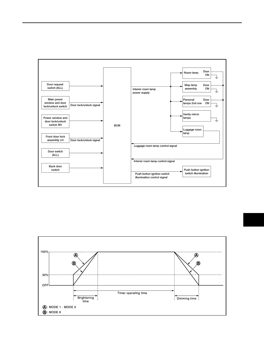
SYSTEM DIAGRAM

OUTLINE

• Interior room lamps* are controlled by interior room lamp timer control function of BCM. 

*: Map lamp assembly and room lamp (when map lamp switch and room lamp switch are in DOOR position).

• Luggage room lamp is controlled by luggage room lamp control function of BCM.

• Push button ignition switch illumination is controlled by the push button ignition switch illumination control

function of BCM.

INTERIOR ROOM LAMP TIMER CONTROL

Interior Room Lamp Timer Basic Operation

NOTE:

A: Sets the interior room lamp gradual brightening and dimming time.

ALLIA1616GB

JMLIA0961GB

INL-8

< SYSTEM DESCRIPTION >

SYSTEM

B: Gradually dims from 100% to 0% and gradually brightens 0% to 100% in 1 second.

• The interior room lamp turns ON and OFF (gradual brightening and dimming) by the interior room lamp

timer.

• The BCM activates the interior room timer with the following vehicle conditions:

- Ignition switch status

- Door switch signal

- Door lock/unlock signal (Remote keyless entry receiver, each door request switch, door lock/unlock switch,

door key cylinder switch)

NOTE:

Each function of interior room lamp timer can be set by CONSULT. Refer to 

BCS-18, "INT LAMP : CONSULT

Function (BCM - INT LAMP)"

 (with Intelligent Key system) or 

BCS-89, "INT LAMP : CONSULT Function (BCM

- INT LAMP)"

 (without Intelligent Key system).

Interior Room Lamp ON Operation:

• BCM always turns the interior room lamp ON when any door opens.

• BCM activates the interior room lamp timer in any of the following conditions to turn the interior room lamp

ON for a period of time:

- Status of all doors changes from open to close

- Ignition switch is turned ON 

→ OFF

- Door unlock signal is detected when all doors close 

NOTE:

The timer restarts if new condition is input during the timer operating time.

Interior Room Lamp OFF Operation:

BCM stops the timer in any of the following conditions to turn the interior room lamp OFF:

• The timer operating time is expired

• Ignition switch is turned OFF 

→ ON

• Door lock signal is detected with all doors close except back door.

LUGGAGE ROOM LAMP CONTROL

BCM turns luggage room lamp ON when the following condition is detected:

• Back door switch is ON

BCM turns luggage room lamp OFF when the following condition is detected:

• Back door switch is OFF

PUSH BUTTON IGNITION SWITCH ILLUMINATION CONTROL

Push Button Ignition Switch Illumination Basic Operation:

BCM provides the power supply to turn the ignition switch illumination ON.

Push Button Ignition Switch Illumination ON Operation

BCM turns the push button ignition switch illumination ON in the following conditions:

• Ignition switch ON

• Any of the following conditions with ignition switch OFF:

- Driver side door is LOCK 

→ UNLOCK

- Driver side door is open

Push Button Ignition Switch Illumination OFF Operation

BCM turns the push button ignition switch illumination OFF in any of the following conditions:

• The push button ignition switch illumination ON conditions are not satisfied.

• Any of the following conditions with the ignition switch OFF:

- The push button ignition switch illumination ON conditions do not change (15 seconds after the ignition

switch OFF)

- Driver side door is UNLOCK 

→ LOCK

INTERIOR ROOM LAMP BATTERY SAVER SYSTEM

SYSTEM

INL-9

< SYSTEM DESCRIPTION >

C

D

E

F

G

H

I

J

K

M

A

B

INL

N

O

P

INTERIOR ROOM LAMP BATTERY SAVER SYSTEM : System Description

INFOID:0000000011279197

SYSTEM DIAGRAM

OUTLINE

• Interior room lamp battery saver is controlled by BCM.

• BCM turns applicable lamps OFF depending on the vehicle condition. This function prevents the 12V battery

from over-discharging if the driver neglects turning OFF the lamps.

Applicable lamps:

• Map lamp assembly

• Room lamp

• Luggage room lamp

• Personal lamps 2nd row 

INTERIOR ROOM LAMP BATTERY SAVER FUNCTION

• When the ignition switch is turned to other position than ON, BCM operates the timer for a period of time to

cut the interior room lamp power supply.

• BCM restarts the timer when any of the following signals changes while operating the timer:

- Ignition switch status

- Door switch signal (ALL)

- Door lock/unlock signal (remote keyless entry receiver, each door request switch, door lock and unlock

switch, door key cylinder switch)

• BCM provides the interior room lamp power supply continuously when the ignition switch position is ON.

NOTE:

Each function of interior room lamp battery saver can be set by CONSULT. Refer to 

BCS-18, "INT LAMP :

CONSULT Function (BCM - INT LAMP)"

 (with Intelligent Key system) or 

BCS-89, "INT LAMP : CONSULT

Function (BCM - INT LAMP)"

 (without Intelligent Key system).

ILLUMINATION CONTROL SYSTEM

ALLIA1619GB

INL-10

< SYSTEM DESCRIPTION >

SYSTEM

ILLUMINATION CONTROL SYSTEM : System Description

INFOID:0000000011279198

SYSTEM DIAGRAM

OUTLINE

Each illumination lamp is controlled by each function of BCM and IPDM E/R.

Controlled by BCM:

• Combination switch reading function

• Headlamp control function

Controlled by IPDM E/R:

• Smart FET control function

Controlled by combination meter:

• Meter illumination control function 

ILLUMINATION CONTROL

• BCM detects the combination switch condition by the combination switch reading function.

• BCM transmits position light request signal to IPDM E/R and combination meter according to tail lamp ON

condition.

Tail lamp ON condition:

- Lighting switch 1ST

- Lighting switch 2ND

- Lighting switch AUTO, and the auto light function ON judgment

- Lighting switch AUTO, with the front fog lamp switch ON and the ignition switch ON

• IPDM E/R turns each illumination lamp ON according to position light request signal. It provides the power

supply to each illumination lamp. 

• Combination meter enters in the nighttime mode according to position light request signal. Under the night-

time mode the combination meter controls the illuminance by controlling the each illumination lamp.

AUTO LIGHT ADJUSTMENT SYSTEM

ALLIA1620GB


Content   ..  793  794  795  796   ..