Nissan Rogue. Manual - part 776


  Index      Nissan     Nissan Rogue (2015 year) - Service and Repair Manual


Search            


Content   ..  774  775  776  777   ..


Nissan Rogue. Manual - part 776


HAC-126

< SYSTEM DESCRIPTION >

[MANUAL AIR CONDITIONING]

DIAGNOSIS SYSTEM (HVAC)

DIAGNOSIS SYSTEM (HVAC)

Description

INFOID:0000000011276674

Air conditioning system performs self-diagnosis, operation check, function diagnosis, and various settings

using diagnosis function of each control unit.

CONSULT Function (HVAC)

INFOID:0000000011276675

CONSULT can display each diagnosis item using the diagnosis test modes as shown. 

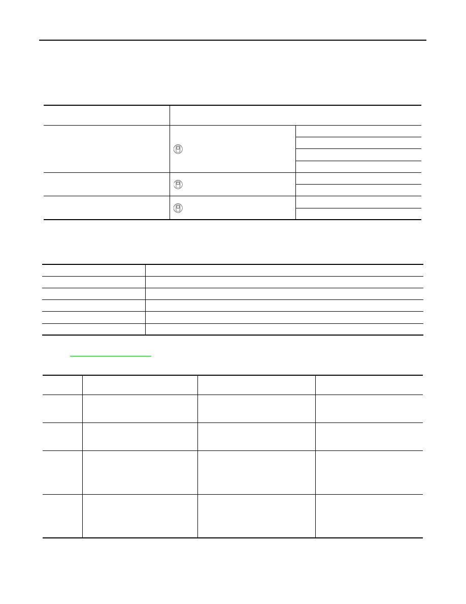
CONSULT application items

SELF DIAGNOSTIC RESULT

Refer to 

HAC-135, "DTC Index"

.

Display Item List

ECU

Diagnostic item

(CONSULT)

Front air control

HVAC

Self Diagnostic Result

Data Monitor

Active Test

Work support

ECM

ENGINE

Self Diagnostic Result

Data Monitor

IPDM E/R

IPDM E/R

Self Diagnostic Result

Data Monitor

Diagnosis mode

Description

Self Diagnostic Result

Displays the diagnosis results judged by A/C auto amp.

Data Monitor

Displays A/C auto amp. input/output data in real time.

Work support

Changes the setting for each system function.

Active Test

The signals used to activate each device are forcibly supplied from front air control.

ECU Identification

Displays the A/C auto amp. number.

DTC

Items

 (CONSULT screen terms)

Diagnostic item is detected when...

Possible cause

U1000

CAN COMM CIRCUIT

When A/C auto amp. is not transmitting 
or receiving CAN communication signal 
for 2 or more seconds.

CAN communication system

U1010

CONTROL UNIT (CAN)

When detecting error during the initial 
diagnosis of CAN controller of front air 
control.

Front air control

B24A4

INTAKE TEMP SEN

Short or open circuit of the intake tem-
perature sensor signal.

• Intake sensor
• Front air control
• Harness and connector

(Intake sensor circuit is open, or 
there is a short in the circuit)

B24BB

AIRMIX ACTR

Short or open circuit of air mix door mo-
tor drive signal.

• Air mix door motor LH
• Front air control
• Harness and connector

(Air mix door motor is open or 
shorted)

DIAGNOSIS SYSTEM (HVAC)

HAC-127

< SYSTEM DESCRIPTION >

[MANUAL AIR CONDITIONING]

C

D

E

F

G

H

J

K

L

M

A

B

HAC

N

O

P

DATA MONITOR

Display item list

WORK SUPPORT

NOTE:
When the battery cable is disconnected from the negative terminal or when the battery voltage becomes 10V or less, the setting of
WORK SUPPORT may be cancelled. 

ACTIVE TEST

HVAC TEST

B24B7

INTAKE ACTR

Short or open circuit of intake door mo-
tor drive signal.

• Intake door motor
• Front air control
• Harness and connector

(Intake door motor is open or 
shorted)

B27B9

MODE DOOR ACTR

Short or open circuit of mode door mo-
tor drive signal.

• Mode door motor
• Front air control
• Harness and connector

(Mode door motor is open or 
shorted)

DTC

Items

 (CONSULT screen terms)

Diagnostic item is detected when...

Possible cause

Monitor item [Unit]

Description

AMB TEMP SEN

[

°C]

Ambient sensor value converted from ambient sensor signal received from ambient 
sensor 

INT TEMP SEN

[

°C] Intake sensor value converted from intake sensor signal received from intake sensor 

AMB SEN CAL

[

°] Ambient sensor value calculated by A/C auto amp.

INT TEMP CAL

[

°C] Intake sensor value calculated by A/C auto amp.

COMP REQ SIG

[On/Off] Displays A/C switch ON/OFF status transmitted to other units via CAN communication

COMP ECV DUTY

[%] Duty ratio of ECV (electrical control valve) judged by A/C amp.

FAN REQ SIG

[On/Off]

Displays blower switch ON/OFF status transmitted to other units via CAN communica-
tion

FAN DUTY

[%] Duty ratio of blower motor judged by A/C auto amp.

VEHICLE SPEED

[km/h

(mph)]

Vehicle speed signal value received from meter via CAN communication

Work item

Description

Reference

Door Motor Starting Position Reset

Starting position reset of air mix door motor and mode door motor 
can be performed. 

HAC-152, "Work Proce-
dure"

TARGET EVAPORATOR TEMP UP-
PER LIMIT SETTING

Set the target evaporator upper temperature limit. 

HAC-151, "Target Evap-
orator Temp Upper Limit"

Test item

Description

HVAC TEST

The operation check of A/C system can be performed by selecting the mode. Refer to the fol-
lowing table for the conditions of each mode.

Test item

MODE 1

MODE 2

MODE 3

MODE 4

MODE 5

MODE 6

MODE 7

Mode door position

VENT

VENT

B/L

B/L

D/F1

D/F2

DEF

Intake door position

REC

REC

20%FRE

20%FRE

FRE

FRE

FRE

Air mix door position

FULL COLD

FULL COLD

FULL COLD

FULL HOT

FULL HOT

FULL HOT

FULL HOT

HAC-128

< SYSTEM DESCRIPTION >

[MANUAL AIR CONDITIONING]

DIAGNOSIS SYSTEM (HVAC)

NOTE:
Perform the inspection of each output device after starting the engine, because the A/C compressor has been operating. 

Blower motor (Applied 
voltage)

35%

35%

60%

60%

90%

90%

35%

A/C compressor (Mag-
net clutch)

ON

ON

ON

ON

OFF

OFF

ON

ECV duty

80%

80%

40%

40%

0%

0%

90%

Test item

MODE 1

MODE 2

MODE 3

MODE 4

MODE 5

MODE 6

MODE 7

DIAGNOSIS SYSTEM (IPDM E/R)

HAC-129

< SYSTEM DESCRIPTION >

[MANUAL AIR CONDITIONING]

C

D

E

F

G

H

J

K

L

M

A

B

HAC

N

O

P

DIAGNOSIS SYSTEM (IPDM E/R)

CONSULT Function (IPDM E/R)

INFOID:0000000011379683

APPLICATION ITEM

CONSULT performs the following functions via CAN communication with IPDM E/R.

ECU IDENTIFICATION

The IPDM E/R part number is displayed.

SELF DIAGNOSTIC RESULT

Refer to 

PCS-22, "DTC Index"

.

DATA MONITOR

Direct Diagnostic Mode

Description

ECU Identification

The IPDM E/R part number is displayed.

Self Diagnostic Result

The IPDM E/R self diagnostic results are displayed.

Data Monitor

The IPDM E/R input/output data is displayed in real time.

Active Test

The IPDM E/R activates outputs to test components.

CAN Diag Support Mntr

The result of transmit/receive diagnosis of CAN communication is displayed.

Monitor Item [Unit]

Description

REVERSE SIGNAL [Open/Close]

Indicates condition of transmission range switch R (Reverse) po-
sition.

IGN RELAY [Open/Close]

Indicates condition of ignition relay-1.

PUSH SW [Open/Close]

Indicates condition of push-button ignition switch.

INTERLOCK/PNP SW [Open/Close]

Indicates condition of transmission range switch P (Park) and N 
(Neutral) positions.

OIL PRESSURE SW [Open/Close]

Indicates condition of oil pressure switch.

HOOD SW [Open/Close]

Indicates condition of hood switch.

COMPRESSOR [OFF/ON]

Indicates condition of A/C compressor.

HORN RELAY [OFF/ ON]

Indicates condition of horn relay.

COOLING FAN [OFF/ON]

Indicates condition of cooling fan relay-1.

FRONT WIPER HI/LO RELAY [OFF/ON]

Indicates condition of front wiper high relay.

FRONT WIPER RELAY [OFF/ON]

Indicates condition of front wiper relay.

IGN RELAY OFF STATUS [OFF/ON]

Indicates condition of ignition relay-1 OFF status.

IGN RELAY ON STATUS [OFF/ON]

Indicates condition of ignition relay-1 ON status.

COOLING FAN RELAY 1 [OFF/ON]

Indicates condition of cooling fan relay-1.

STARTER RELAY [OFF/ON]

Indicates condition of starter relay.

COMP ECV DUTY [%]

Indicates condition of A/C compressor.

COOLING FAN RELAY 2 [%]

Indicates condition of cooling fan relay-2.

FR FOG LAMP LH [%]

Indicates condition of front fog lamp LH.

FR FOG LAMP RH [%]

Indicates condition of front fog lamp RH.

PARKING LAMP [%]

Indicates condition of parking lamp.

TAIL LAMP LH [%]

Indicates condition of tail lamp LH.

TAIL LAMP RH [%]

Indicates condition of tail lamp RH.

DAYTIME RUNNING LIGHT LH [%]

Indicates condition of daytime running light LH.

DAYTIME RUNNING LIGHT RH [%]

Indicates condition of daytime running light RH.

HEADLAMP (HI) LH [%]

Indicates condition of headlamp high beam LH.


Content   ..  774  775  776  777   ..