Nissan Rogue. Manual - part 774
 

  Index      Nissan     Nissan Rogue (2015 year) - Service and Repair Manual


Search            


Content   ..  772  773  774  775   ..


Nissan Rogue. Manual - part 774


HAC-118

< SYSTEM DESCRIPTION >

[MANUAL AIR CONDITIONING]

SYSTEM

SYSTEM

System Description

INFOID:0000000011276666

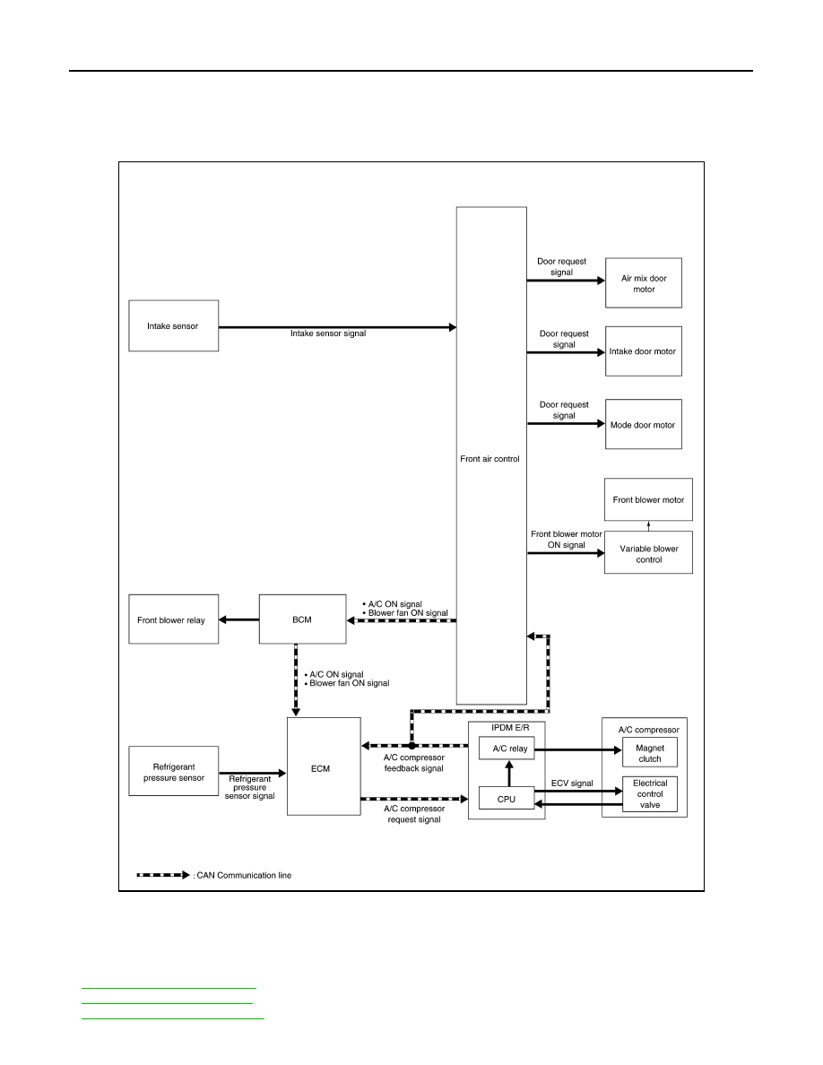
SYSTEM DIAGRAM

SYSTEM DESCRIPTION

• The manual air conditioning system is controlled by a sequence of functions from the front air control, BCM,

ECM, and IPDM E/R.

Controlled by front air control:

-

HAC-119, "Air Flow Control"

-

HAC-119, "Air Inlet Control"

-

HAC-119, "Air Outlet Control"

ALIIA0909GB

SYSTEM

HAC-119

< SYSTEM DESCRIPTION >

[MANUAL AIR CONDITIONING]

C

D

E

F

G

H

J

K

L

M

A

B

HAC

N

O

P

-

HAC-119, "Compressor Control"

-

HAC-120, "Door Control"

-

HAC-123, "Temperature Control"

Controlled by BCM:

- Air conditioning request signal.

Refer to 

BCS-8, "BODY CONTROL SYSTEM : System Description"

 (with Intelligent Key system) or 

BCS-80,

"BODY CONTROL SYSTEM : System Description"

 (without Intelligent Key system).

Control by ECM

- Cooling fan control

Refer to 

EC-48, "COOLING FAN CONTROL : System Description"

.

- Air conditioning cut control

Refer to 

EC-47, "AIR CONDITIONING CUT CONTROL : System Description"

.

Control by IPDM E/R

- Relay control

Refer to 

PCS-7, "RELAY CONTROL SYSTEM : System Description"

.

- Cooling fan control

Refer to 

EC-48, "COOLING FAN CONTROL : System Description"

.

Air Flow Control

INFOID:0000000011276667

DESCRIPTION

• Front air control changes duty ratio of front blower motor control signal to control air flow continuously. When

air flow is increased, duty ratio of front blower motor control signal gradually increases to prevent a sudden

increase in air flow.

• In addition to manual control, air flow control is composed of fan speed control at door motor operation.

FAN SPEED CONTROL AT DOOR MOTOR OPERATION

When mode door motor is activated while air flow is more than the specified value, front air control temporarily

reduces fan speed so that mode door moves smoothly.

Air Inlet Control

INFOID:0000000011276668

The intake door position is automatically controlled in MAX A/C and DEF modes. The intake door is controlled

by customer input in the other modes.

Air Outlet Control

INFOID:0000000011276669

Air outlet control is controlled by customer input. When the A/C is turned off by turning the blower control dial

fully counterclockwise, the front air control retains the current selections and returns to these selections the

next time the blower control dial is turned to any fan position.

NOTE:

If ambient temperature is excessively low, D/F is selected to prevent windshield fogging when air outlet is set

to FOOT.

Compressor Control

INFOID:0000000011276670

DESCRIPTION

In order for the IPDM E/R to complete a compressor ON request, the following conditions must be met:

1. The BCM detects a Fan ON signal from the front air control. The front air control grounds the fan ON sig-

nal monitored by the BCM when the blower speed dial is in any of the fan speed positions.

2. The BCM detects an A/C ON signal from the front air control. The front air control grounds the A/C ON sig-

nal monitored by the BCM when:

-

The A/C switch is pressed. The A/C switch LED illuminates and the front air control grounds the A/C ON

signal monitored by the BCM. Any mode control button except D/F may be selected. 

-

The A/C switch is OFF, and the MAX A/C button is pressed. The A/C switch LED will automatically illumi-

nate and the front air control grounds the A/C ON signal monitored by the BCM. 

-

The A/C switch is OFF, and the mode button for either D/F or DEF is selected. The front air control

grounds the A/C ON signal monitored by the BCM, but it does not illuminate the A/C switch LED

HAC-120

< SYSTEM DESCRIPTION >

[MANUAL AIR CONDITIONING]

SYSTEM

NOTE:

If the compressor was engaged by pressing the D/F or DEF mode buttons, and the time spent in either mode

exceeds 1 minute, then the compressor stays requested, even when modes other than D/F or DEF are

selected, until either:

1. The ignition switch is turned OFF.

2. The blower speed dial is turned completely counterclockwise to the OFF position.

3. The A/C switch is manually turned OFF.

In other words, the compressor ON request cannot be turned off in D/F or DEF modes.

REFRIGERANT PRESSURE PROTECTION

The refrigerant system is protected against excessively high- or low-pressures by the refrigerant pressure sen-

sor, located on the liquid tank on the condenser. The refrigerant pressure sensor detects the pressure inside

the refrigerant line and sends a voltage signal to the ECM. If the system pressure rises above or falls below

the following values, the ECM requests the IPDM E/R to de-energize the A/C relay and disengage the com-

pressor.
• 3.12 MPa (31.82 kg/cm

2

, 452.4 psi) or more (When the engine speed is less than 1,500 rpm)

• 2.74 MPa (27.95 kg/cm

2

, 397.3 psi) or more (When the engine speed is 1,500 rpm or more)

• 0.14 MPa (1.43 kg/cm

2

, 20.3 psi) or less

PRESSURE RELIEF VALVE

The refrigerant system is also protected by a pressure relief valve, located in the rear head of the compressor.

When the pressure of refrigerant in the system increases to an abnormal level [more than 2,990 kPa (30.5 kg/
cm

2

, 433.6 psi)], the release port on the pressure relief valve automatically opens and releases refrigerant into

the atmosphere.

COMPRESSOR OIL CIRCULATION CONTROL

When the engine starts while the engine coolant temperature is 56

°C (133°F) or less, ECM activates the com-

pressor for approximately 6 seconds and circulates the compressor lubricant once.

LOW TEMPERATURE PROTECTION CONTROL

• When the intake sensor detects that the front evaporator fin temperature is 1.5

°C (35°F) or less, the front air

control requests the BCM to turn the compressor OFF, and stops the compressor.

• When the front evaporator fin temperature returns to 5.0

°C (41°F) or more, the compressor is activated.

OPERATING RATE CONTROL

When the set temperature is other than fully cold or the air outlet is “VENT”, “B/L” or “FOOT”, the front air con-

trol controls the compressor activation depending on ambient temperature.

Door Control

INFOID:0000000011276671

AIR MIX DOOR MOTOR

DESCRIPTION

• The step motor system is adopted for air mix door motor.

• When a drive signal is input from front air control to door motor, a step motor built into the door motor rotates

according to the drive signal, and then stops at the target door position.

• Rotation of motor is transmitted to air mix door (upper air mix door and lower air mix door) by link, rod and

lever, then air flow temperature is switched.

DRIVE METHOD

• The 4 drive coils are excited in sequence in order to drive the motor.

SYSTEM

HAC-121

< SYSTEM DESCRIPTION >

[MANUAL AIR CONDITIONING]

C

D

E

F

G

H

J

K

L

M

A

B

HAC

N

O

P

• Direction of rotation is changeable by recomposing pattern of excitation.

MODE DOOR MOTOR

DESCRIPTION

• The step motor system is adopted for mode door motor.

• When a drive signal is input from front air control to door motor, a step motor built into the door motor rotates

according to the drive signal, and then stops at the target door position.

• Rotation of motor is transmitted to mode door (center ventilator and defroster door, sub defroster door, side

ventilator door, and foot door) by link, rod, and lever, then air outlet is switched.

DRIVE METHOD

• The 4 drive coils are excited in sequence in order to drive the motor.

• Direction of rotation is changeable by recomposing pattern of excitation.

INTAKE DOOR MOTOR

• Motor operates intake door according to control signal from front air control.

• Rotation of motor is transmitted to intake door by lever, then air inlet is switched.

SWITCHES AND THEIR CONTROL FUNCTION

JSIIA1655GB

JZIIA0033GB


Content   ..  772  773  774  775   ..